
Method and apparatus for measuring multiple parameters of steam

a technology of multiple parameters and steam, which is applied in the direction of survey, instruments, borehole/well accessories, etc., can solve the problems of high cost of well operation, high cost of steam generation and maintenance, and the inability of electrical cables and optical fiber cables to directly withstand such high temperatures

Inactive Publication Date: 2003-01-07
PHOTOSONIC
View PDF10 Cites 32 Cited by
  • Summary
  • Abstract
  • Description
  • Claims
  • Application Information

AI Technical Summary

Problems solved by technology

It is estimated that as much as two thirds of the oil in existing reservoirs cannot be recovered, due to difficulties in measuring downhole environmental conditions.
However, the cost of generating and maintaining the steam to recovering the crude oil deposits accounts for a high percentage of the total cost of well operation, and the equivalent of as much as one-third of the total crude oil recovered is required to produce the steam that is required for the recovery process.
Currently available electrical cables and optical fiber cables cannot directly withstand such high temperatures because their cabling and jacketing materials would be melted immediately.
The combined effects of high temperature and pressure make the fabrication of the sensing apparatus even more difficult, because they may cause high stress on the materials, which may result in inaccurate measurements.
Previously, no apparatus or method has yet been successfully developed for the measurement of even one parameter, except fluid-flow, in steam injection wells, even though great efforts have been attempted.
Because the boiling points of most working media are below 350.degree. C., and the temperature of saturated steam is 400.degree. C., this approach has significant difficulties.
However, the spinner flowmeter has a minimum flow velocity sensitivity of about 2 to 4 feet / minute in wells of 4-inch or larger diameter and is not capable of measuring slow fluid flows.

Method used


Image

  • Method and apparatus for measuring multiple parameters of steam
  • Method and apparatus for measuring multiple parameters of steam
  • Method and apparatus for measuring multiple parameters of steam

Examples


Embodiment Construction

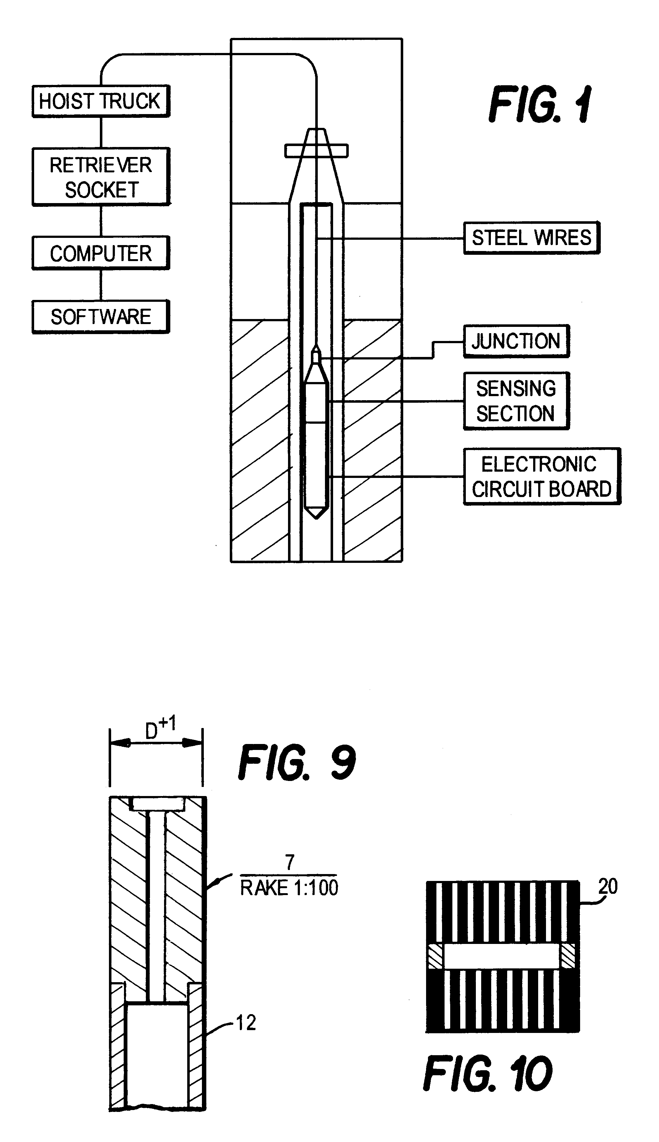
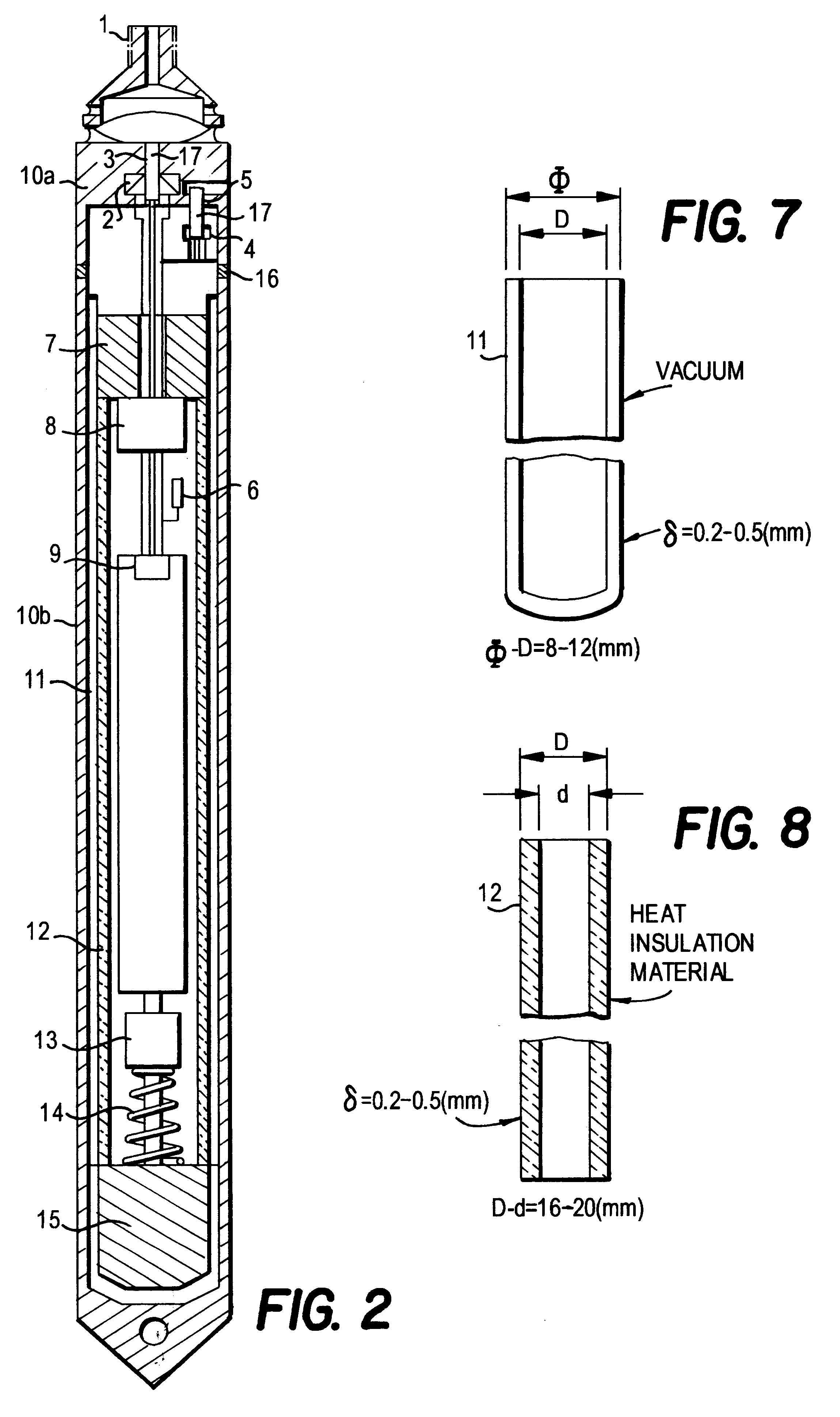
The present invention is a significant development in fiber optic sensors, apparatus, and methods for performing quantitative measurements of the aridity, temperature, fluid-flow rate, total pressure, still pressure, and kinetic pressure of steam in harsh environments. It is not practical to approximate or simulate the conditions of high-temperature and high-pressure since there is no physical law available that can be used to explain such conditions. Here an empirical formula is employed:

P=P1-P2 (1)

-P=(1 / 2).rho.v.sup.2 (2)

Where P is the kinetic pressure, P1 is the total pressure, P2 is the still pressure, .rho. is the aridity or steam density, and v is the flow rate of the steam. As steam moves inside transmission pipes, the pressure measured is the total pressure, which includes both still pressure and kinetic pressure, whereas when the steam does not move, the pressure measured is the still pressure.

For a general understanding of the present invention, reference will now be made ...


PUM

PropertyMeasurementUnit
temperatureaaaaaaaaaa
pressuresaaaaaaaaaa

Abstract

A method and an apparatus are disclosed for the measurement of the aridity, temperature, flow rate, total pressure, still pressure, and kinetic pressure of steam at a downhole location within a well through which wet steam is flowing. The apparatus comprises a series of fiber optic sensors that are mounted on sections of a shell assembly. The apparatus is lowered into a well to different downhole locations, and measures the multiple parameters of steam at different locations and heights. The data can be stored on board for subsequent analysis at the surface when the apparatus is retrieved from the well. The apparatus is very reliable, accurate, and of long-life in harsh environments.

Description

BACKGROUND--FIELD OF INVENTIONThe present invention relates generally to a method and an apparatus for measuring the aridity, temperature, flow rate, total pressure, still pressure, and kinetic pressure of steam at a downhole location within a well through which wet steam is flowing.BACKGROUND PRIOR ARTIn the exploration and production of crude oil, it is often found that the crude oil is too viscous to be recovered, so in many cases, saturated steam has to be injected into the petroleum wells to dilute and force the thick oil out of the downhole wells, thus these wells are called steam injection wells. It is estimated that as much as two thirds of the oil in existing reservoirs cannot be recovered, due to difficulties in measuring downhole environmental conditions. However, the cost of generating and maintaining the steam to recovering the crude oil deposits accounts for a high percentage of the total cost of well operation, and the equivalent of as much as one-third of the total c...

Claims


Application Information

Patent Timeline
Patent Type & Authority Patents(United States)
IPC IPC(8): E21B43/24E21B43/16G01L19/08G01L19/00G01D5/26G01D5/34G01N33/18G01N25/56G01N25/60
CPCE21B43/24G01D5/344G01N33/18G01N25/60G01L19/083
Inventor CHEN, YAOSHENG
Owner PHOTOSONIC
Learn More