Write head driver circuit and method for writing to a memory disk

a write head and memory disk technology, applied in pulse generators, instruments, pulse techniques, etc., can solve problems such as reducing the effective rate at which data can be accurately written and read, and difficulty in distinguishing successive magnetic transitions

Inactive Publication Date: 2003-01-07
STMICROELECTRONICS SRL
View PDF16 Cites 25 Cited by
  • Summary
  • Abstract
  • Description
  • Claims
  • Application Information

AI Technical Summary

Problems solved by technology

Since the disk is moving relative to the head, it can be seen that if the small space separating the magnetic domain transitions is not sufficiently wide, difficulty may be encountered in distinguishing successive magnetic transitions.
This may result in errors in reading the data contained on the disk, which is, of course, undesirable.
However, since the data signals are in the form of square wave transitions, if the rise time of the leading edges of the square waves is large, the small space between magnetic media transitions also becomes large, which reduces the effective rate at which data can be accurately written and read.
Since the write head assembly includes at least one coil, forcing the current to rise rapidly, or to reverse flux directions within the write head is difficult.
As a result, voltage spikes or other voltage transitions appearing on the lines connected to write head coil 19 may have a greater tendency to appear as noise on the lines connected to the read head of the disk drive and potentially damage the read head as a result.
As can be seen, this relatively sizeable voltage spike may be capacitively coupled to the lines associated with the read head of the disk drive and thereby damage the read head.
In addition, the voltage spikes appearing on the write head terminals occur at substantially the same time and are in opposite directions, thereby tending to offset the noise caused by each.

Method used


Image

  • Write head driver circuit and method for writing to a memory disk
  • Write head driver circuit and method for writing to a memory disk
  • Write head driver circuit and method for writing to a memory disk

Examples


first embodiment

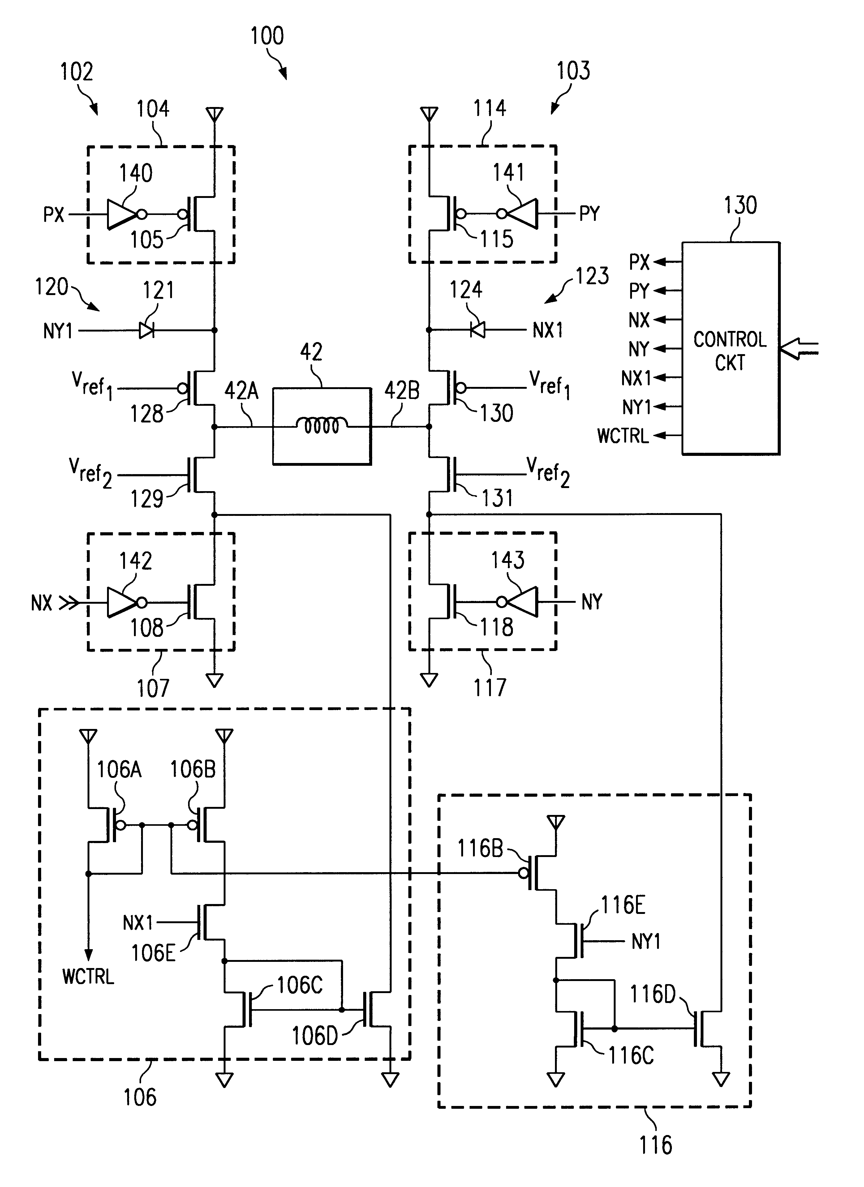
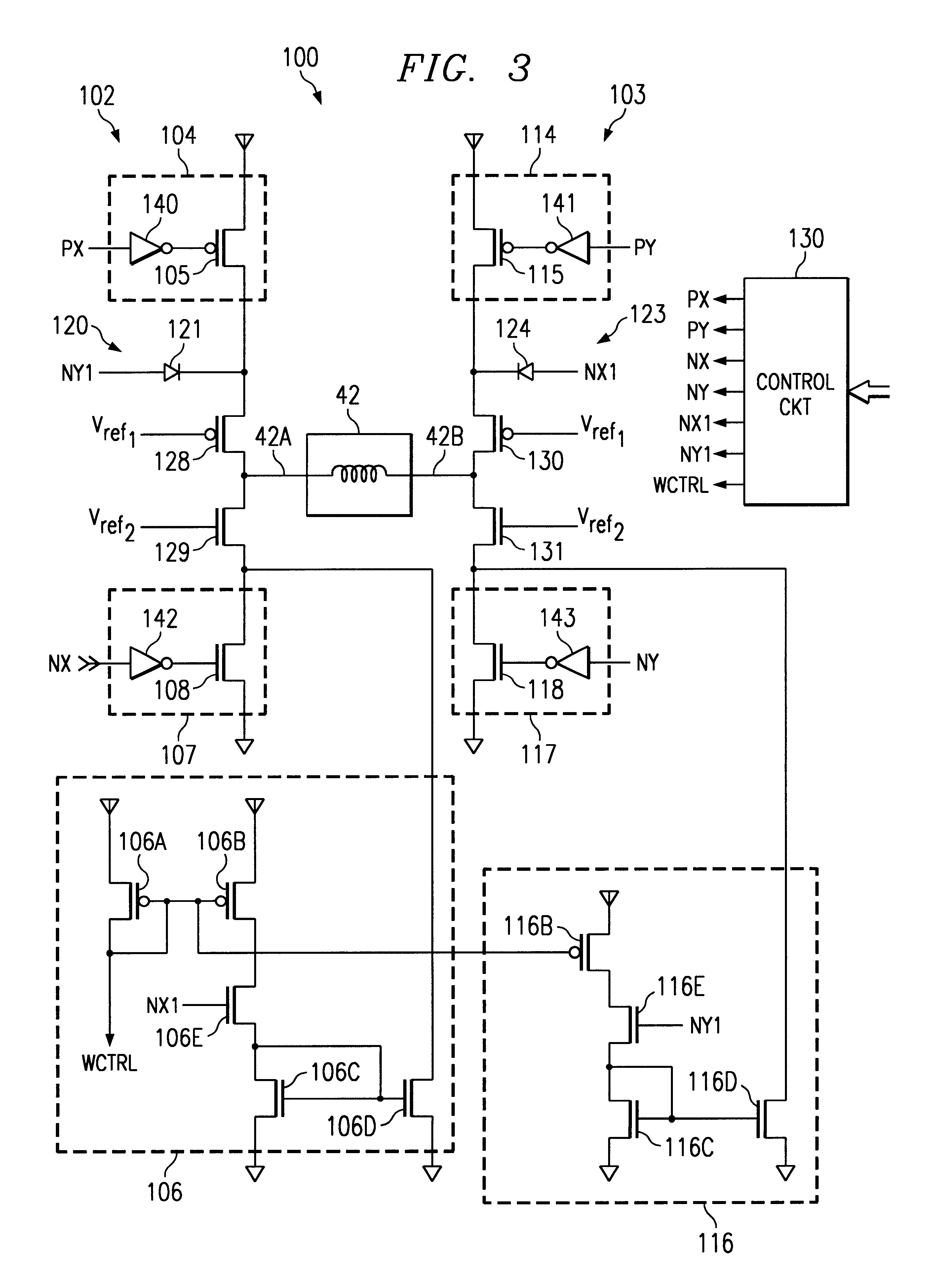
In the present invention shown in FIG. 3, clamp device 120 is a diode 121 having a cathode coupled to write head terminal 42A and an anode connected to control signal NY1. Diode 121 is activated by control signal NY1 having a voltage level that forward biases diode 121. When forward biased, diode 121 clamps the voltage appearing on write head terminal 42A to a p-n junction voltage less than the voltage level appearing on control signal NY1.

second embodiment

In the present invention shown in FIG. 4, clamp device 120 is a transistor 122 having a first conduction (source) terminal coupled to write head terminal 42A, and a second conduction (drain) terminal coupled to a reference voltage level Vc, such as a voltage level between high reference voltage level Vdd and low reference voltage level Vss. Transistor 122 is activated by control signal Pe being driven to a voltage level to turn on transistor 122. Once turned on, a conduction path exists between reference voltage level Vc and the write head terminal 42A, thereby serving to clamp write head terminal 42A to approximately reference voltage level Vc.

It is understood that clamp device 120 may be formed of other components to clamp write head terminal 42A to a desired voltage level.

Sub-circuit 102 of driver circuit 100 includes a pull-up device 104 connected between terminal 42A of write head 42 and high reference voltage, Vdd. In a preferred embodiment of the present invention, pull-up de...


PUM

PropertyMeasurementUnit
currentaaaaaaaaaa
voltage levelsaaaaaaaaaa
voltageaaaaaaaaaa

Abstract

A method and circuit are disclosed for controlling the write head of a magnetic disk storage device. The circuit includes a pull-up device and a current sink circuits coupled to each terminal of the write head, for selectively sourcing current to and sinking current from the write head, respectively. A clamp device is coupled to each write head terminal to selectively clamp the write head terminals to steady state intermediate voltage levels. The circuit further includes a control circuit for individually activating the pull-up devices, the current sink circuits and the clamp devices. In particular, when reversing the direction of current flow through the write head from a first direction in which current is provided to the write head via the write head terminal to a second direction in which current is drawn from the write head from the write head terminal, the appropriate pull-up device is activated for a predetermined period of time. The clamp device coupled to the temporarily activated pull-up device is thereafter activated to clamp the corresponding write head terminals to the steady state intermediate voltage levels.

Description

1. Technical Field of the InventionThe present invention relates to circuit and method for writing to a memory disk, and particularly to a circuit and method for driving the write head of a disk drive device.2. Background of the InventionMost computer systems include one or more associated disk drives, which may be built into or external to the computer system. Typically, disk drives have at least one rotating magnetic medium and associated head mechanisms that are carried adjacent the magnetic material. The heads are radially positionable to selectively write information to, or read information from, precise positions on the disk medium. Such disk drives may be, for example, hard disk drives, floppy drives, or the like.Data is written to the associated data disk by applying a series of signals to a write head according to the digital information to be stored on the magnetic disk media. The write head has a coil and one or more associated pole pieces that are located in close proxim...

Claims


Application Information

Patent Timeline
Patent Type & Authority Patents(United States)
IPC IPC(8): G11B5/02G11B5/00G11B5/09G11B5/012
CPCG11B5/02G11B5/022G11B5/012G11B2005/0013G11B5/09
Inventor PATTI, GIUSEPPEALINI, ROBERTO
Owner STMICROELECTRONICS SRL
Why Eureka
Try Eureka