

Electronic equipment enclosure
a technology for electronic equipment and enclosures, which is applied in the direction of electrical apparatus enclosures/cabinets/drawers, electrical apparatus connection, electrical apparatus construction details, etc., can solve the problems of many prior art equipment enclosures, inability to maneuver the mounted equipment enclosure for easy access to the interior, and undetectable mounting orientation limitations
- Summary
- Abstract
- Description
- Claims
- Application Information
AI Technical Summary
Benefits of technology
Problems solved by technology
Method used
Image

Examples
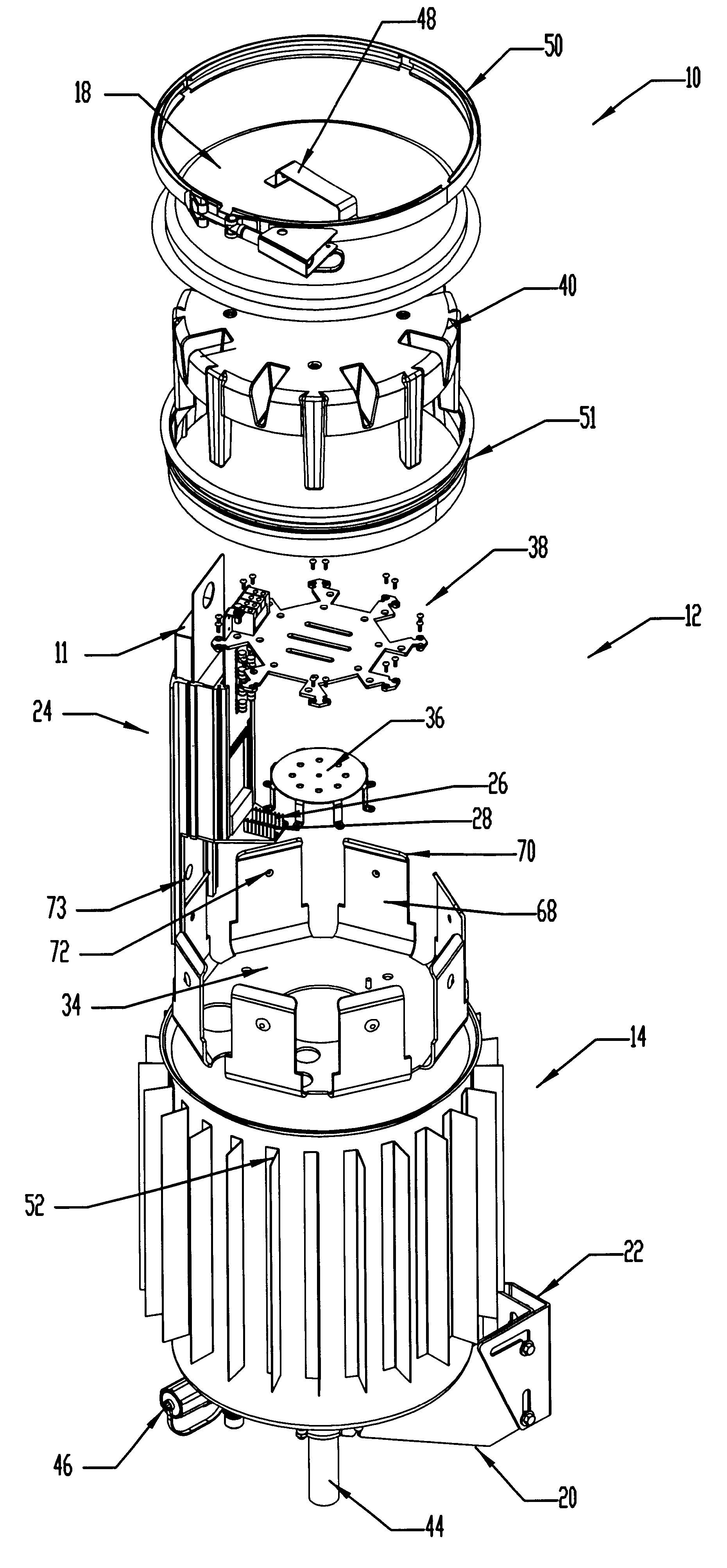
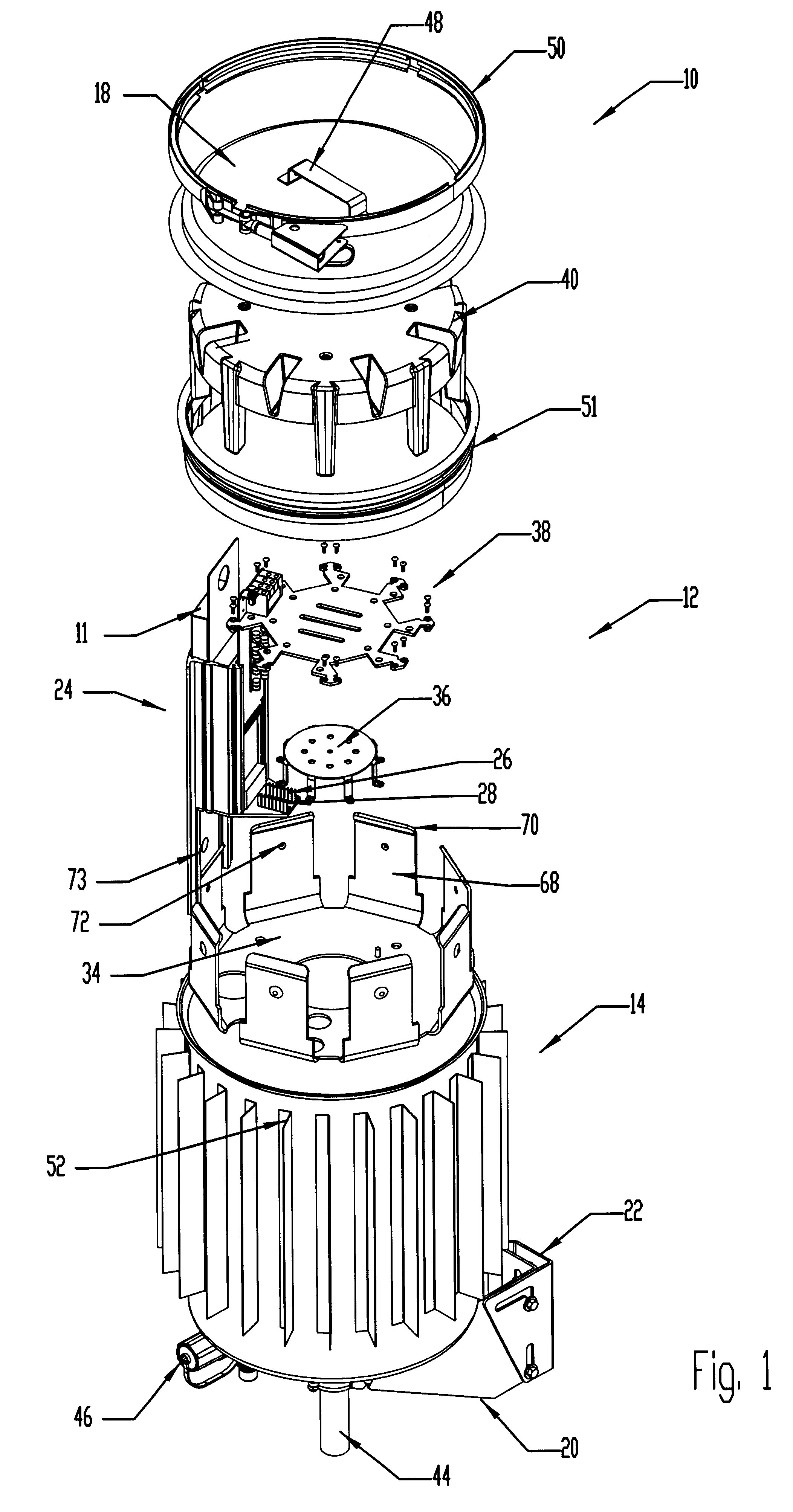
first embodiment
FIG. 1 is an exploded isometric view of a preferred first embodiment of the electronic equipment enclosure of the present invention;
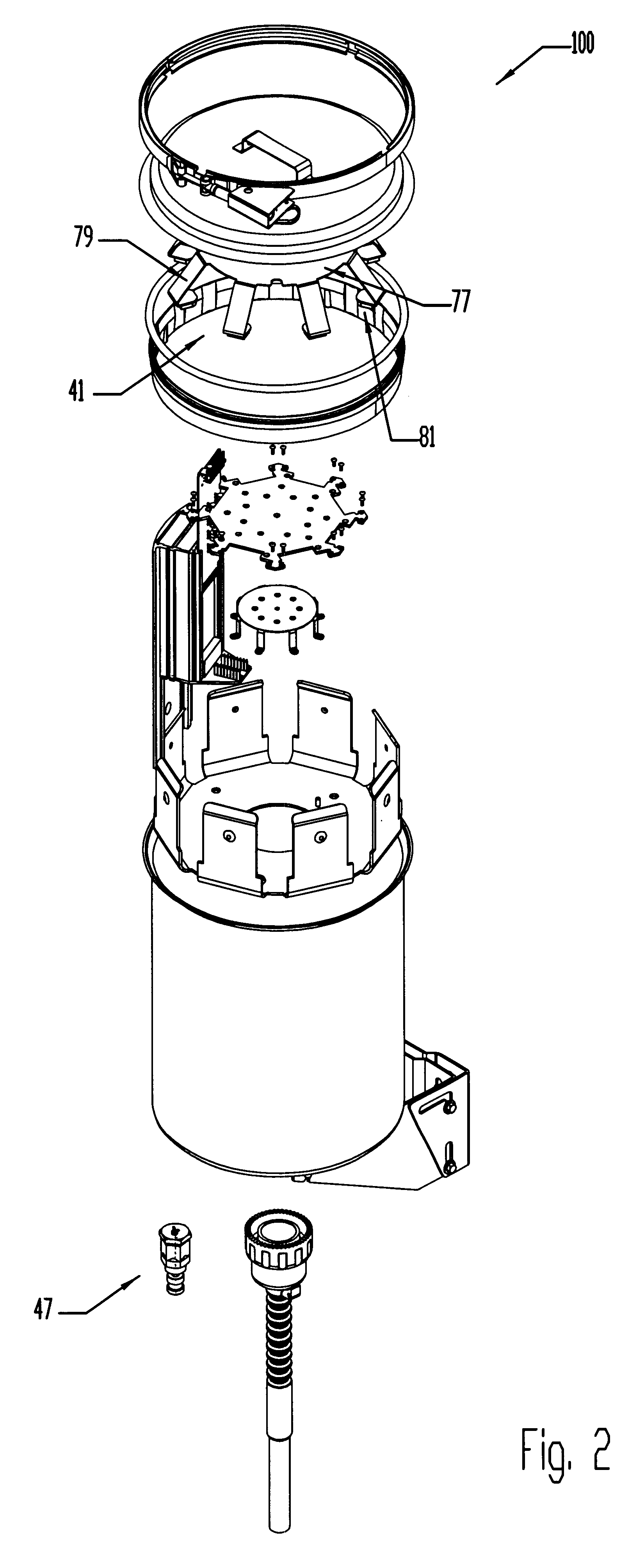
second embodiment
FIG. 2 is an exploded isometric view of a preferred second embodiment of the electronic equipment enclosure of the present invention;
FIG. 3 is an exploded isometric view of a pivot bracket portion of the present invention;
FIG. 4 is an exploded isometric view of a sleeve portion and sleeve spreader portion of the present invention;
FIG. 5 is an isometric view of a heat sink portion of the present invention;
FIG. 6 is an isometric view of a card retainer portion of the present invention;
FIG. 7 is a top plan view looking into an open outer housing portion of the embodiment shown in FIG. 1, showing a number of the sleeves arranged about an interior of the outer housing; and
FIG. 8 is a top plan view looking into an open outer housing portion of the embodiment shown in FIG. 2, showing a number of the sleeves arranged about an interior of the outer housing.
PUM
 Abstract
Description
Claims
Application Information