
Apparatus for depositing a material by evaporation on large surface substrates

a technology of evaporation and substrate, which is applied in the manufacture of electrode systems, cold cathode manufacturing, electric discharge tubes/lamps, etc., can solve the problems of large substrate size, inconvenient type of apparatus for depositing, and inability to maintain a high deposition rate. , to achieve the effect of adequate deposition rate and small vapour incidence angl

Inactive Publication Date: 2003-01-21
XANTIMA
View PDF17 Cites 12 Cited by
  • Summary
  • Abstract
  • Description
  • Claims
  • Application Information

AI Technical Summary

Benefits of technology

is to solve the aforementioned problem, i.e. to propose a simple apparatus making it possible to make deposits on large substrates and making it possible to maintain a relatively small vapour incidence angle and an adequate deposition rate for an industrial process.
The use of several sources makes it possible to decrease the distance between the evaporation source and the substrate and consequently the height of the system. Moreover, the means for channelling or piping to the substrate the vapours emitted by the sources make it possible to limit the incidence angle of the vapour which is condensed on the substrate. Thus, it is possible to simultaneously decrease the source-substrate distance and the angle of incidence of the vapour. The sources are placed directly facing the substrate and directly see the substrate or a portion thereof.
In particular, the movement can be a planetary rotary movement of the substrate. A planetary rotary movement of the substrate on itself and about an axis called the central axis of the evaporation system makes it possible to achieve a very good uniformity.

Problems solved by technology

However, problems arise when the size of the substrates is increased.
It is therefore of interest to reduce the distance h between the source and the substrate and a distance of 3.16 m is unacceptable for maintaining a high deposition rate.
This type of apparatus is not suitable for producing deposits on substrates having a large surface.
However, this type of apparatus is incompatible with industrial production, particularly on large substrates.
In particular, the nozzles can progressively become clogged by parasitic material deposits.
This also leads to evaporated material flow rate variations.
Finally, the apparatuses described in the aforementioned documents involve ionization and acceleration sections and are consequently complex.
Such uniformity problems can in particular occur as a result of the vapour piping means.
The non-uniformity can also be due to variable deposition rates between individual points of the substrate.

Method used


Image

  • Apparatus for depositing a material by evaporation on large surface substrates
  • Apparatus for depositing a material by evaporation on large surface substrates
  • Apparatus for depositing a material by evaporation on large surface substrates

Examples


first embodiment

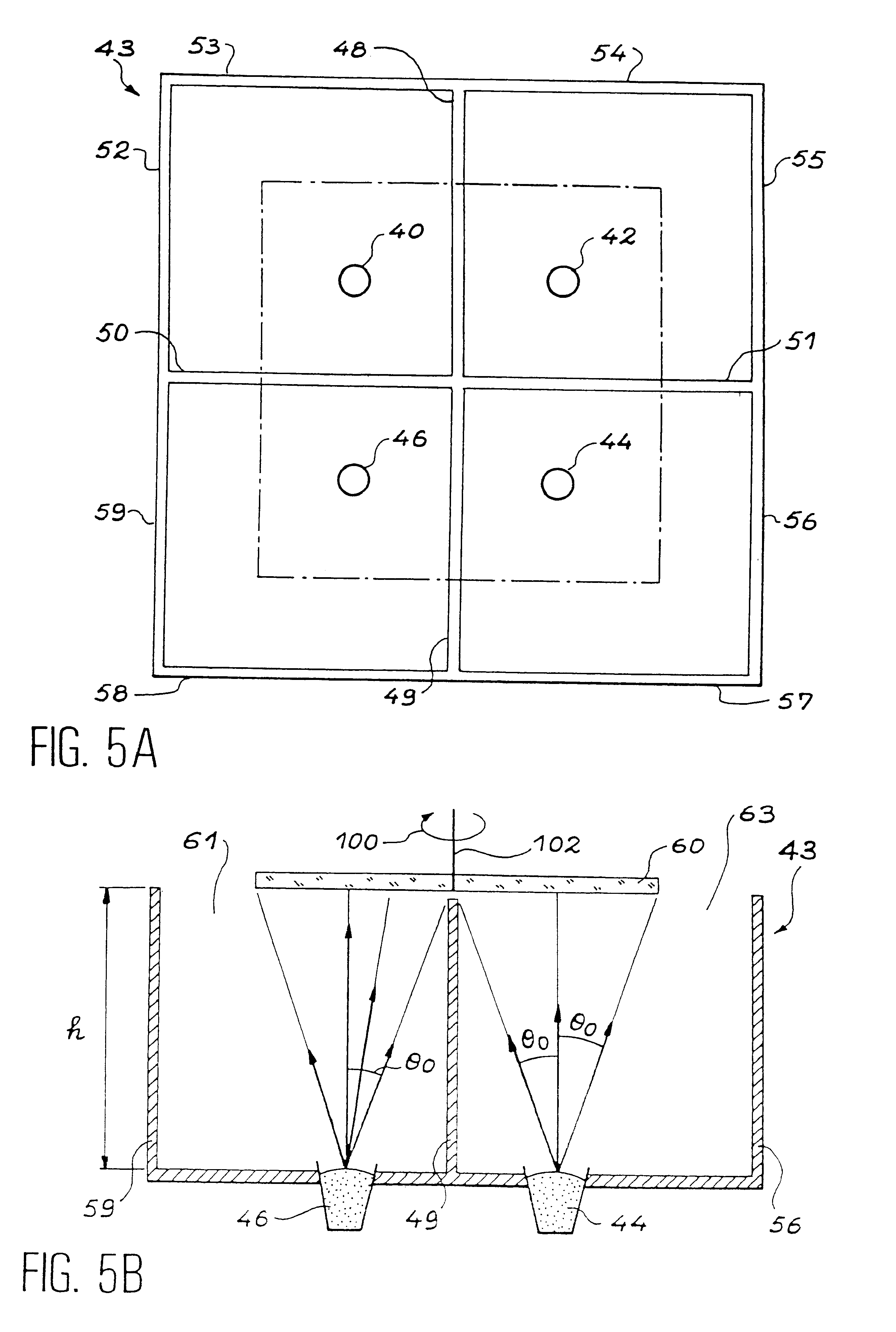
the invention will be described in conjunction with FIGS. 5A and 5B, which respectively show a plan view and a sectional view of an apparatus according to the invention.

Said apparatus essentially comprises an enclosure 43 having, in the embodiment illustrated in the drawings, an approximately square section. This enclosure is bounded by walls 52, 53, . . . , 59. This enclosure is subdivided into four compartments by walls 48, 49, 50, 51. At the bottom of each of these compartments is provided an evaporation source 40, 42, 44, 46. A surface or substrate 60 can be introduced into the top of the enclosure 43 and installed on a not shown substrate holder in such a way that the deposit surface is at a distance h from the bottom of the enclosure 43. The presence of the different vertical walls makes it possible to prevent material being evaporated on the surface of the substrate with an angle exceeding the angle .theta..sub.0 shown in FIG. 5B. It is consequently possible to make a deposit...


PUM

PropertyMeasurementUnit
thicknessaaaaaaaaaa
heightaaaaaaaaaa
heightaaaaaaaaaa

Abstract

An apparatus for depositing a material by evaporation on a substrate having a large surface. The apparatus includes an enclosure in which are placed a number of material evaporation sources. It also includes a device for channeling or piping of vapors emitted by the sources toward the substrate during evaporation. This is formed by walls or covers which define compartments within the enclosure, each evaporation source being placed in a compartment. The apparatus can also utilize a device for moving the substrate in order to improve the uniformity of the deposit.

Description

1. Field of the InventionThe present invention relates in general terms to the deposition of material by evaporation on a substrate having a large size. One application is the production of microtip or microdot electron sources using field effect electron emission, said sources being of large size. Said electron sources are e.g. used in field emission-excited cathodoluminescence display means and in particular in flat screens of large size (approximately 1 m.sup.2).2. Discussion of the BackgroundA microtip emissive system and its production process are e.g. described in detail in FR-A-2 593 953 of Jan. 24, 1986 and in FR-A-2 663 462 of Jun. 13, 1990. Firstly a description will be given of the known procedure for producing such microtips in a structure of this type, such as can be gathered from the aforementioned document by referring to the enclosed FIGS. 1, 2 and 3.FIG. 1 shows an already produced structure having on a substrate 6 surmounted by an insulator 7, a system of cathode c...

Claims


Application Information

Patent Timeline
Patent Type & Authority Patents(United States)
IPC IPC(8): C23C14/24C23C14/50H01J9/02
CPCC23C14/24H01J9/025C23C14/505C23C14/243
Inventor IDA, MICHELPERRIN, AIMEBOREL, MICHELCHARLES, RAYMOND
Owner XANTIMA
Learn More