Method for differentially writing to a memory disk

a memory disk and differential writing technology, applied in the field of differential writing to a memory disk, can solve the problems of reducing the effective rate at which data can be accurately written and read, difficulty in distinguishing successive magnetic transitions, and errors in reading data contained on the disk

Inactive Publication Date: 2003-01-28
STMICROELECTRONICS SRL +1
View PDF16 Cites 11 Cited by
  • Summary
  • Abstract
  • Description
  • Claims
  • Application Information

AI Technical Summary

Problems solved by technology

Since the disk is moving relative to the head, it can be seen that if the small space separating the magnetic domain transitions is not sufficiently wide, difficulty may be encountered in distinguishing successive magnetic transitions.
This may result in errors in reading the data contained on the disk, which is, of course, undesirable.
However, since the data signals are in the form of square wave transitions, if the rise time of the leading edges of the square waves is large, the small space between magnetic media transitions also becomes large, which reduces the effective rate at which data can be accurately written and read.
Since the write head assembly includes at least one coil, forcing the current to rise rapidly, or to reverse flux directions within the write head is difficult.
One problem encountered in disk drives employing existing drive circuitry for the wr

Method used


Image

  • Method for differentially writing to a memory disk
  • Method for differentially writing to a memory disk
  • Method for differentially writing to a memory disk

Examples


Embodiment Construction

The present invention will now be described more fully hereinafter with reference to the accompanying drawings in which a preferred embodiment of the invention is shown.

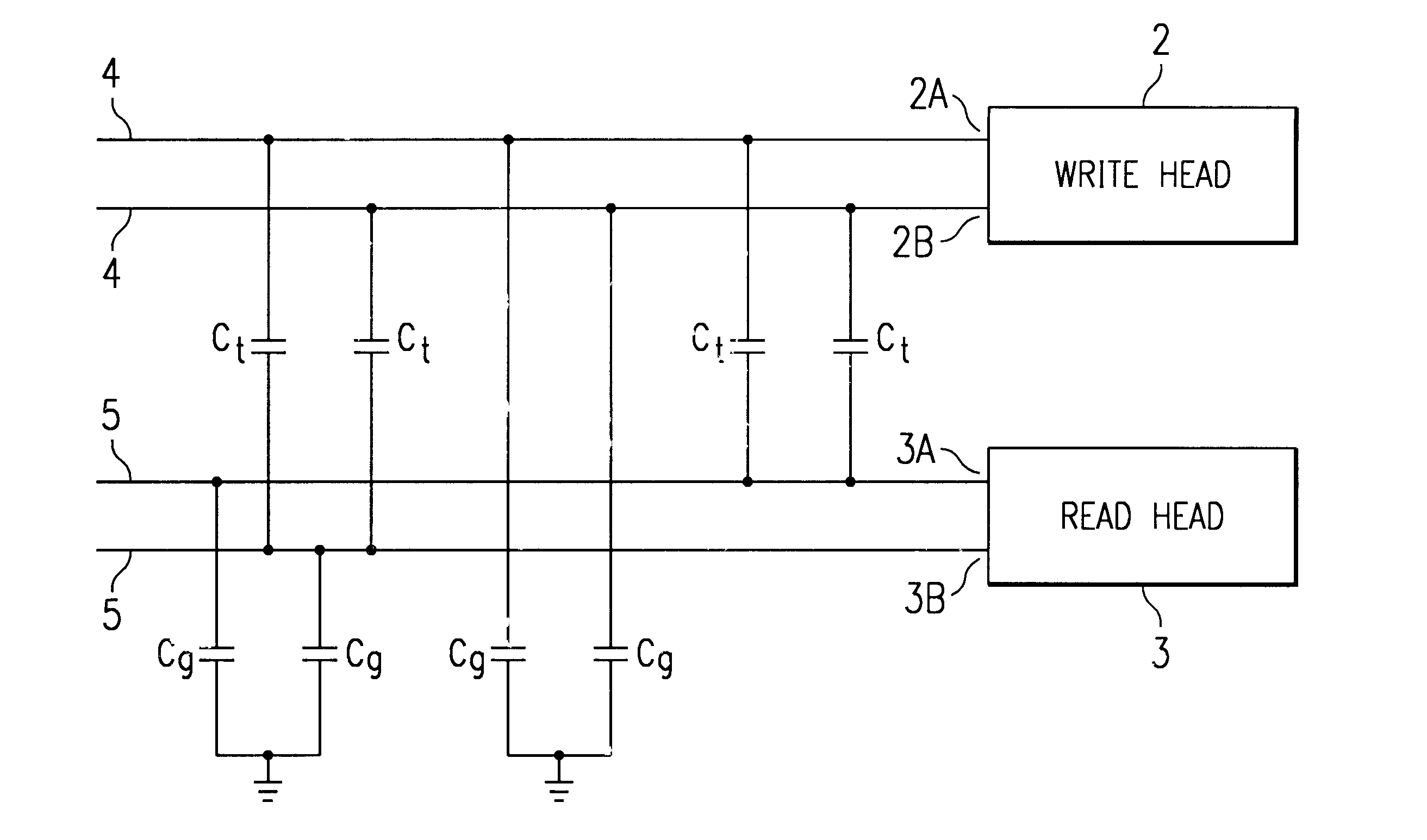
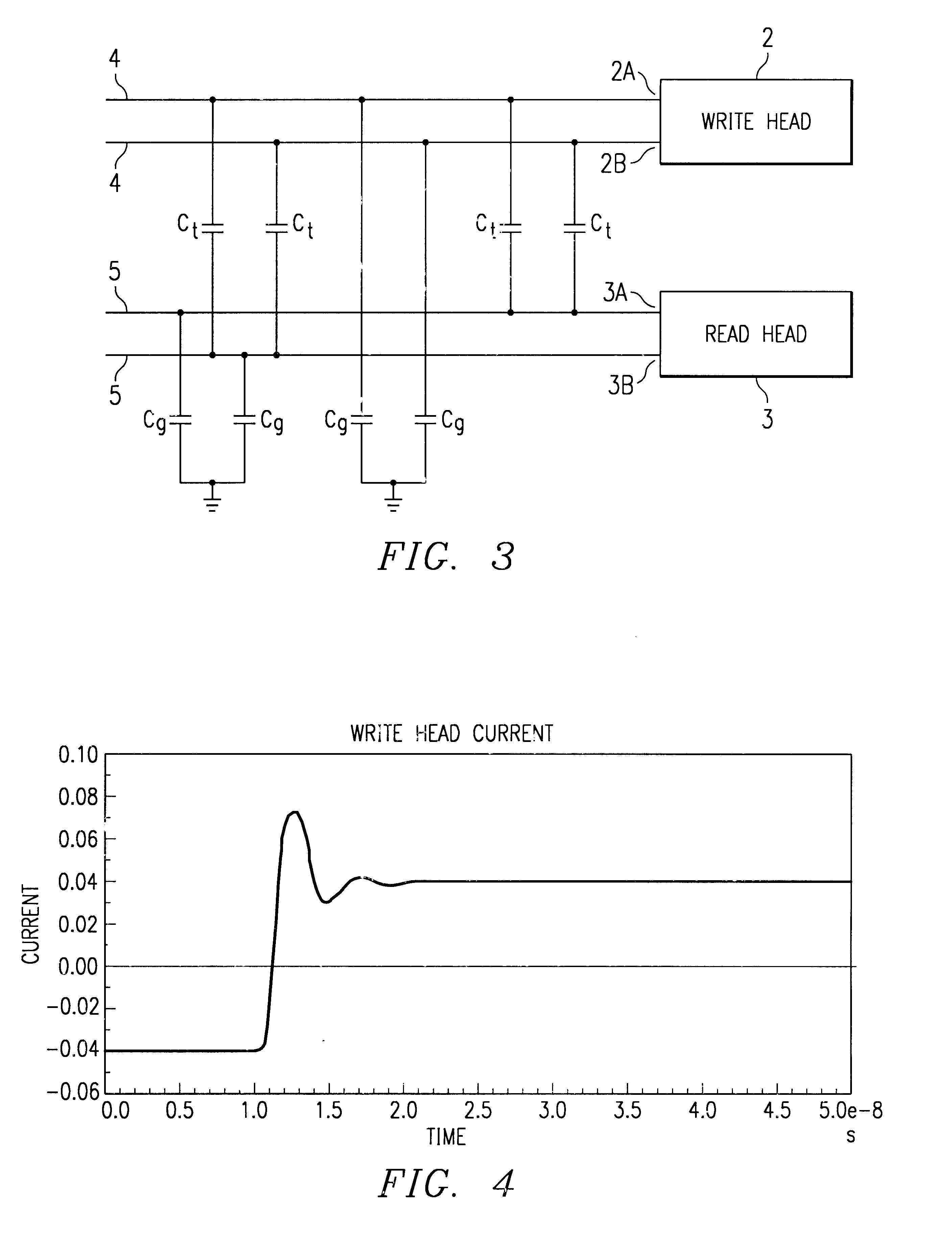
Referring to FIG. 3, the disk drive 1 includes a write head 2 having a first terminal 2A and a second terminal 2B. The disk drive 1 further includes a read head 3 having a first terminal 3A and a second terminal 3B. A preamplifier circuit (not shown) includes output signals connected to the first and second terminals of write head 2 via write head lines 4, and input signals connected to the first and second terminals of read head 3 via read head lines 5. Due to the close proximity between write head lines 4 and read head lines 5, read head lines 5 are directly capacitively coupled to write head lines 4. The direct capacitive coupling between write head lines 4 and read head lines 5 is represented as capacitors C.sub.t.

It is understood that write head lines 4 may be capacitively coupled to other signal lines within a ...


PUM


Abstract

A method is disclosed for controlling the write head of a magnetic disk storage device. The method includes sinking current from the first terminal of the write head and sourcing current to the second terminal of the write head substantially simultaneously with sinking current from the first terminal so that a first steady state voltage level appears on the first terminal of the write head and a second steady state voltage level appears on the second terminal thereof that are approximately at a midpoint between a high reference voltage level and a low reference voltage level. The common mode voltage of the write head is substantially constant over time.

Description

Description of the Related ArtThe present invention relates to a method for writing to a memory disk, and particularly to a method for controlling the write head of a disk drive device.Most computer systems include one or more associated disk drives, which may be built into or external to the computer system. Typically, disk drives have at least one rotating magnetic medium and associated head mechanisms that are carried adjacent the magnetic material. The heads are radially positionable to selectively write information to, or read information from, precise positions on the disk medium. Such disk drives may be, for example, hard disk drives, floppy drives, or the like.Data is written to the associated data disk by applying a series of signals to a write head according to the digital information to be stored on the magnetic disk media. The write head has a coil and one or more associated pole pieces that are located in close proximity to the disk media. As signals cause the magnetic ...

Claims


Application Information

Patent Timeline
IPC IPC(8): G11B5/09G11B5/02G11B5/40G11B5/00G11B5/012
CPCG11B5/02G11B5/022G11B5/40G11B5/09G11B5/012G11B2005/0013G11B2005/001
Inventor ALINI, ROBERTOLAM, QUOCDZUNG T.CHEW, XIAOKUN LIUMCCORNACK, MARKBEZINQUE, DAVID JOSEPHLEE, TEHRILE, SU DANGDE LA SOUJEOLE, AXEL ALEGREDENOYER, GILLES
Owner STMICROELECTRONICS SRL
Why Eureka
Try Eureka