Torque sensor

Inactive Publication Date: 2003-02-04
CONTINENTAL AUTOMOTIVE GMBH
View PDF19 Cites 21 Cited by
  • Summary
  • Abstract
  • Description
  • Claims
  • Application Information

AI Technical Summary

Benefits of technology

This configuration permits the entire rotation angle sensing device to be arranged to be stationary in relation to the measuring shaft. Consequently, the entire evaluation of the rotation angle sensing can take place directly on the measuring shaft. The risk that interference will be introduced into the signals is relatively low. The electrical power which is necessary to operate the processing device is supplied on an optical path. The power supply device converts the incident luminous flux into an electrical voltage and, if appropriate, conditions this voltage. Since no relatively large amounts of electrical power are usually required for the signal processing in the rotation angle sensing device, the optical power, transmitted with the aid of light, is entirely sufficient.
In a particularly preferred configuration, provision is made for the measuring shaft to be surrounded by a hollow shaft which bears one of the two carriers, the other carrier being of circular-segment design and projecting through a corresponding slot in the wall of the hollow shaft. This has the advantage that the hollow shaft can be supported on both sides of the measuring shaft. The movement of the hollow shaft in relation to the measuring shaft is then restricted to pure rotation. Consequently, the result is no other displacements of the two carriers in relation to each other. Since one carrier is of circular-segment design, it is able to project through the slot in the hollow shaft without excessively weakening the hollow shaft.

Problems solved by technology

The risk that interference will be introduced into the signals is relatively low.

Method used


Image

  • Torque sensor
  • Torque sensor

Examples


Embodiment Construction

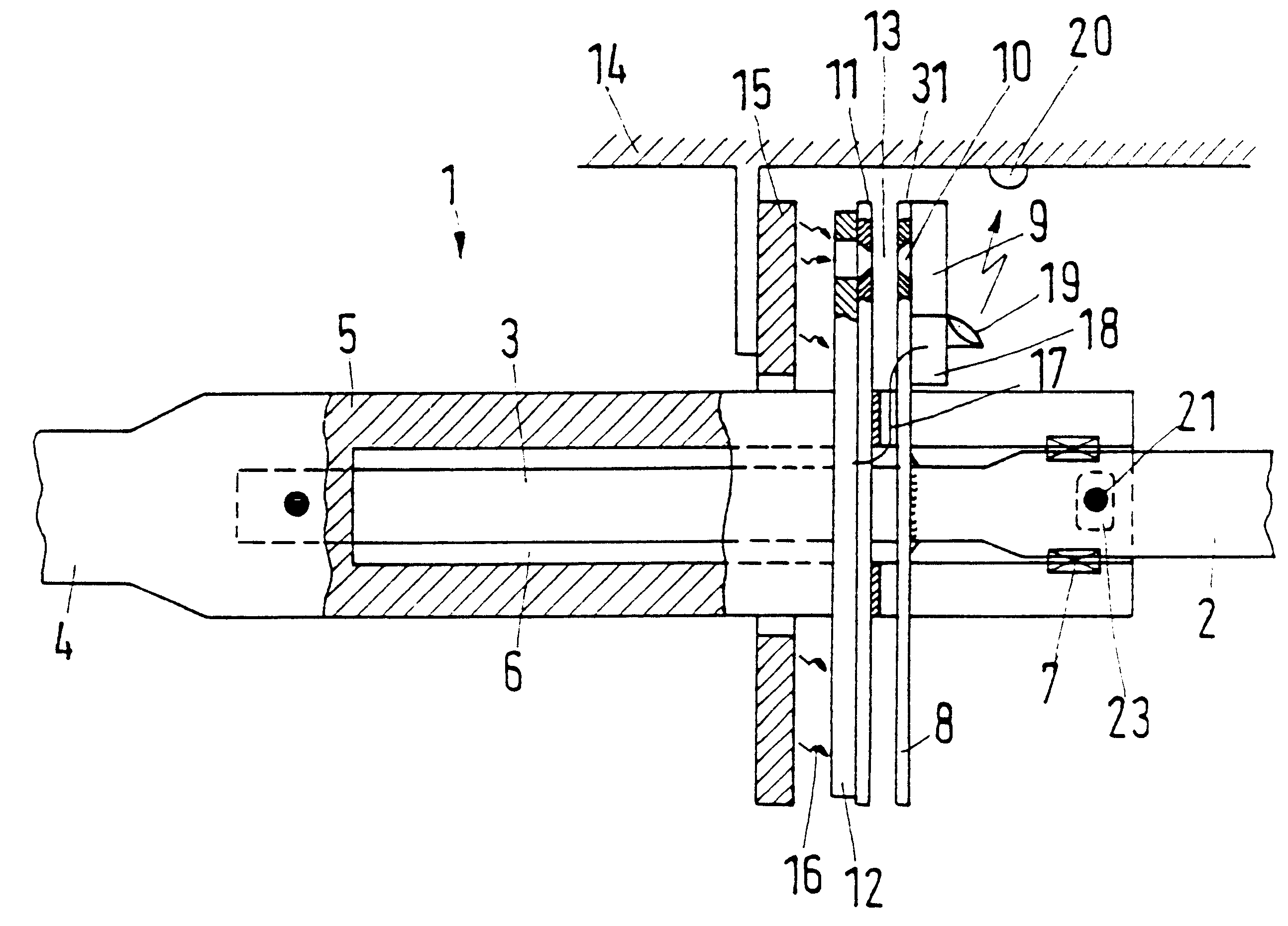
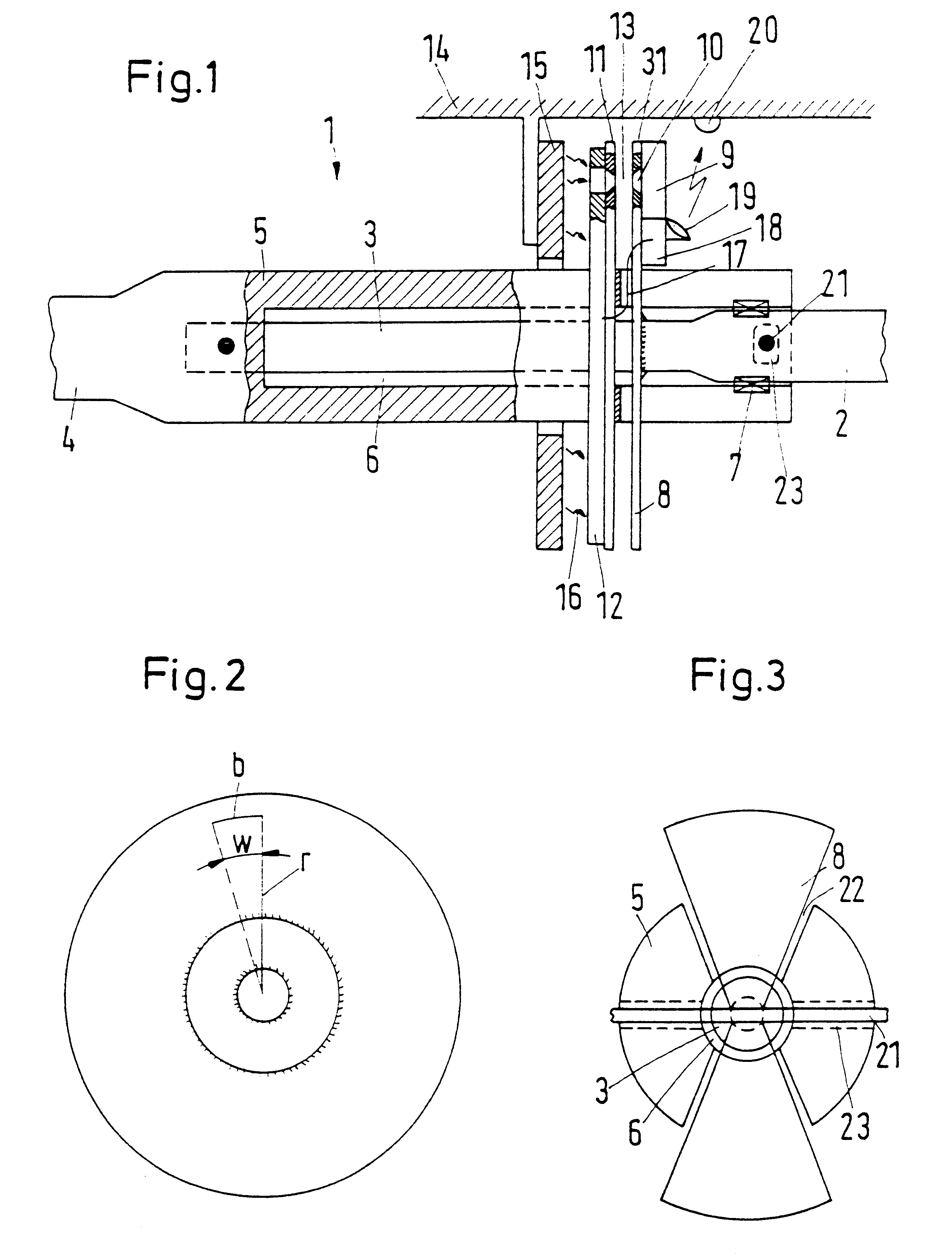
A torque sensor 1 is used to determine a torque on a steering shaft. One portion 2 of the steering shaft, which is connected to a steering wheel (not specifically illustrated), is connected via a measuring shaft 3, which is designed as a torsion shaft, to a second portion 4, which is connected to a steering gearbox (not specifically illustrated). If the portion 2 of the steering shaft is rotated, the measuring shaft 3 then transmits the corresponding torque to the portion 4, which rotates accordingly. If the steered wheels are to be moved from one extreme position to the other, then as a rule between three and eight revolutions of the steering shaft are necessary for this.

Fastened to the portion 4 of the steering shaft is a sleeve 5, which is designed as a hollow shaft. The measuring shaft 3 is arranged in the hollow interior 6 of the sleeve 5. The measuring shaft 3 has a diameter which is reduced by comparison with the two portions 2, 4. The sleeve 5 extends over the entire length ...


PUM


Abstract

A torque sensor has a housing which has a light source and a measuring shaft which has a signal generator arrangement belonging to a rotation angle sensing device with a processing The rotation angle sensing device is arranged to rotate relative to the housing, together with the measuring shaft, and the processing device has an opto-electric power supply device.

Description

1. Field of the InventionThe present invention relates to a torque sensor having a housing which has a light source and a measuring shaft which has a signal generator arrangement associated with a rotation angle sensing device with a processor.2. Description of the Related ArtA torque sensor of this type is disclosed by EP 0 555 987 B1. The known torque sensor is used in a power-assisted vehicle steering system. It is arranged between a steering wheel and a steering gearbox. The wheels are acted on by a motor which is driven in such a way that the torque determined by the torque sensor becomes as small as possible. The measuring shaft is in this case designed as a torsion shaft, that is to say it is rotated or twisted somewhat when a force is applied to the steering wheel. The signal generator arrangement operates optically. It has two diaphragm disks which, when a torque occurs, are rotated in relation to each other. A receiver arrangement receives a greater or lesser luminous flux...

Claims


Application Information

Patent Timeline
IPC IPC(8): G01L5/22G01L3/12
CPCG01L5/221G01L3/12
Inventor GUTJAHR, JORGPORTH, WOLFGANGGIER, LUTHER
Owner CONTINENTAL AUTOMOTIVE GMBH
Why Eureka
Try Eureka