
Mode-conversion method for model railroad decoders

a technology of mode conversion and model railroad, applied in the direction of dynamo-electric converter control, multiple dynamo-motor starters, instruments, etc., to achieve the effect of not causing damag

Inactive Publication Date: 2003-02-04
IRELAND ANTHONY JOHN
View PDF7 Cites 18 Cited by
  • Summary
  • Abstract
  • Description
  • Claims
  • Application Information

AI Technical Summary

Benefits of technology

Since 1997 Digitrax Inc. has produced DCC decoders with the unique ability to test the state of the motor isolation from the track connections at initial power-on. This is a novel fault detection method that finds and protects against the most common reason that decoder installations fail. This is the failure by the installer to remove the original locomotive motor to track connections from both of the motor leads correctly and hence allow the motor to powered solely by the decoder H-bridge output circuit. If any failure of isolation is detected, the Digitrax decoder will disable the H-bridge output circuit from driving the motor and no damage can occur to the H-bridge or decoder, since it will not be able to conflict with the track energy source, even though the decoder and H-bridge are also being powered by the track energy. It is also possible for the decoder to signal this measured and assumed fault state by blinking lights in a distinctive manner.
This protection method is very useful in allowing for a new and innovative way of forcing an accurate mode-conversion capability on the decoder. Since the motor leads may be selectively connected by simple jumpers to both the track and the decoder H-bridge output connections at the same time, without damaging the decoder, it is possible to use this direct metallic jumper connection to allow the motor to run accurately on conventional track power or energy. Since the decoder actively detects this state and responds in a safe and suitable manner, no ill effects will occur when the track power is also simultaneously jumper-connected to the motor in this manner, and the normal higher startup voltage of the decoder will not affect the accuracy of the motor speed operation. The unpowered state of the decoder and H-bridge is designed to be nonconductive to the motor output terminals. When the conventional track power is sufficient for the decoder to begin operation, the motor will typically already be in motion and the decoder will detect the track-motor jumpers and decline to operate the H-bridge output.
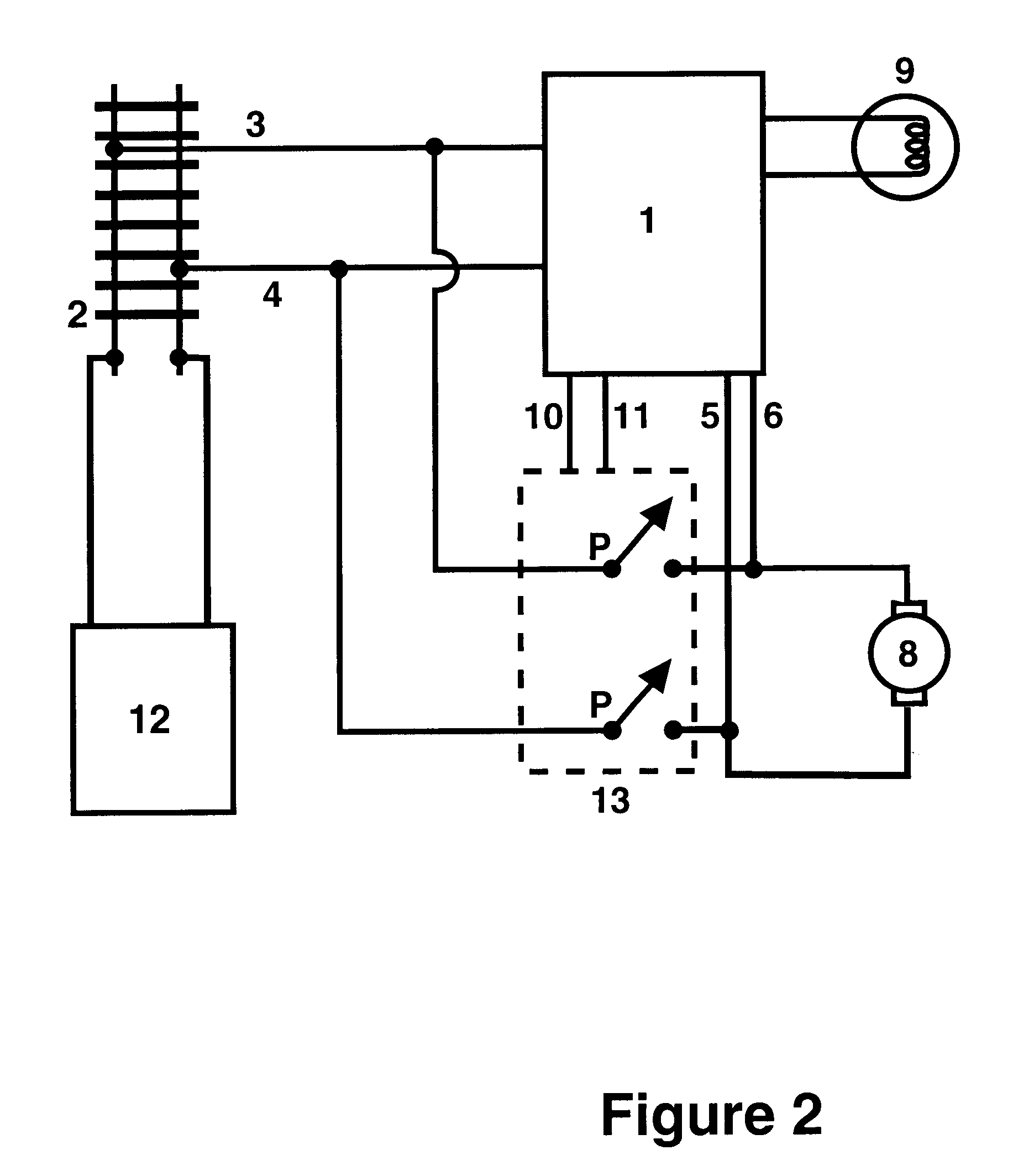
This new configuration disclosed herein is distinctly different to that of Kosinski, NMRA RP-9.1.1 and Graf, in that the decoder is definitely powered simultaneously to the motor and the decoder H-bridge output circuit is also always connected to the motor leads, irrespective of whether or not the track energy is also connected to the motor. This new configuration only needs two simple and inexpensive make-break jumpers or switch connections, and only four connection points are used to switch the currents, unlike the 6 connection points per switch of the double-pole changeover types of arrangements used in the prior art. This minimizes; the number of current carrying terminals, wire connections needed, Printed Circuit Board connection area and also improves reliability. This also allows the use of lower cost make-break or single throw type standard DIP switches or "form A" reed relays to effect the conversion.

Problems solved by technology

This is the failure by the installer to remove the original locomotive motor to track connections from both of the motor leads correctly and hence allow the motor to powered solely by the decoder H-bridge output circuit.

Method used


Image

  • Mode-conversion method for model railroad decoders
  • Mode-conversion method for model railroad decoders
  • Mode-conversion method for model railroad decoders

Examples


Embodiment Construction

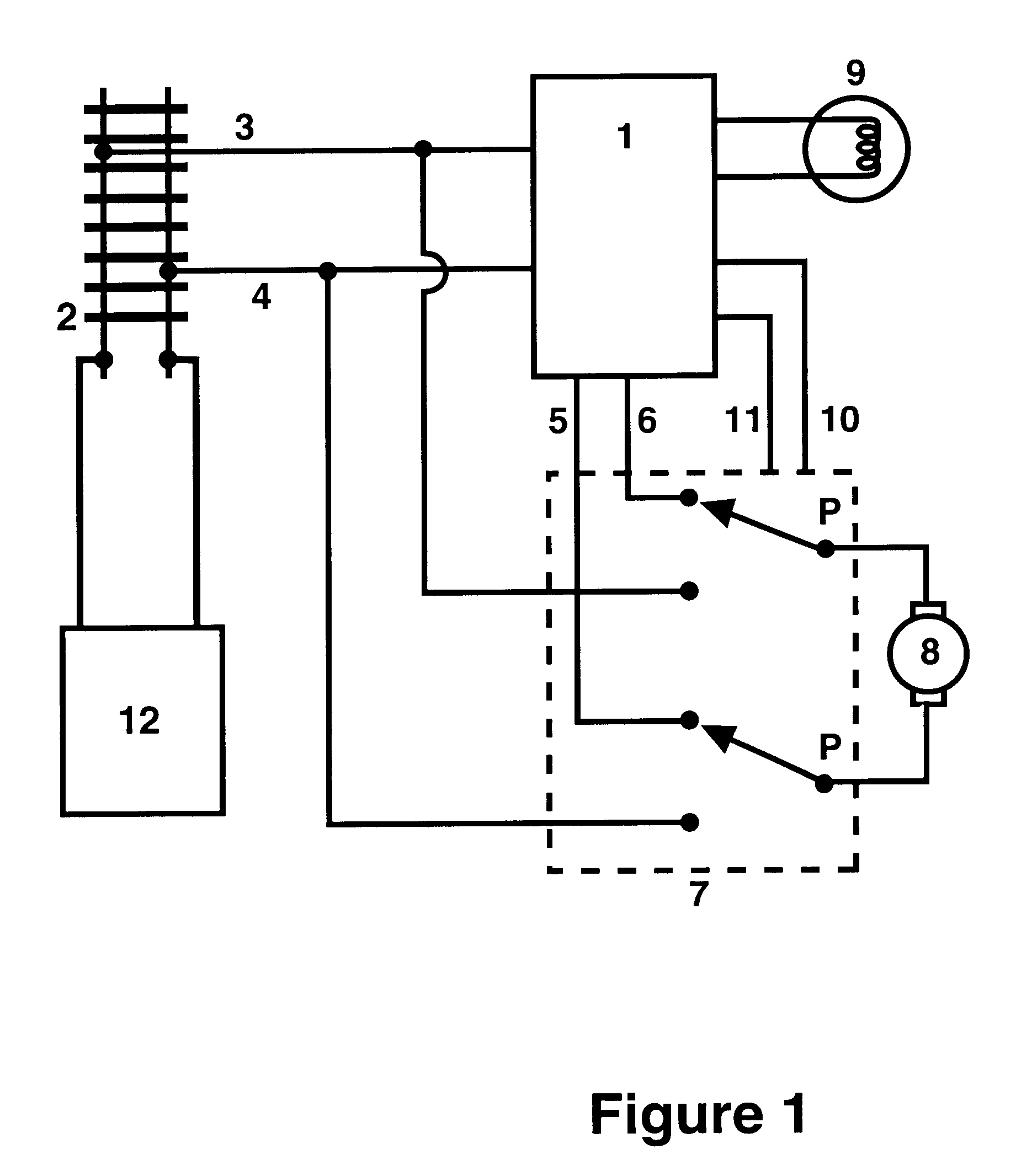
FIG. 1 depicts many key elements of the general electrical connection arrangement of the prior art of RP-9.1.1 and also represents some of the configuration described by Graf.

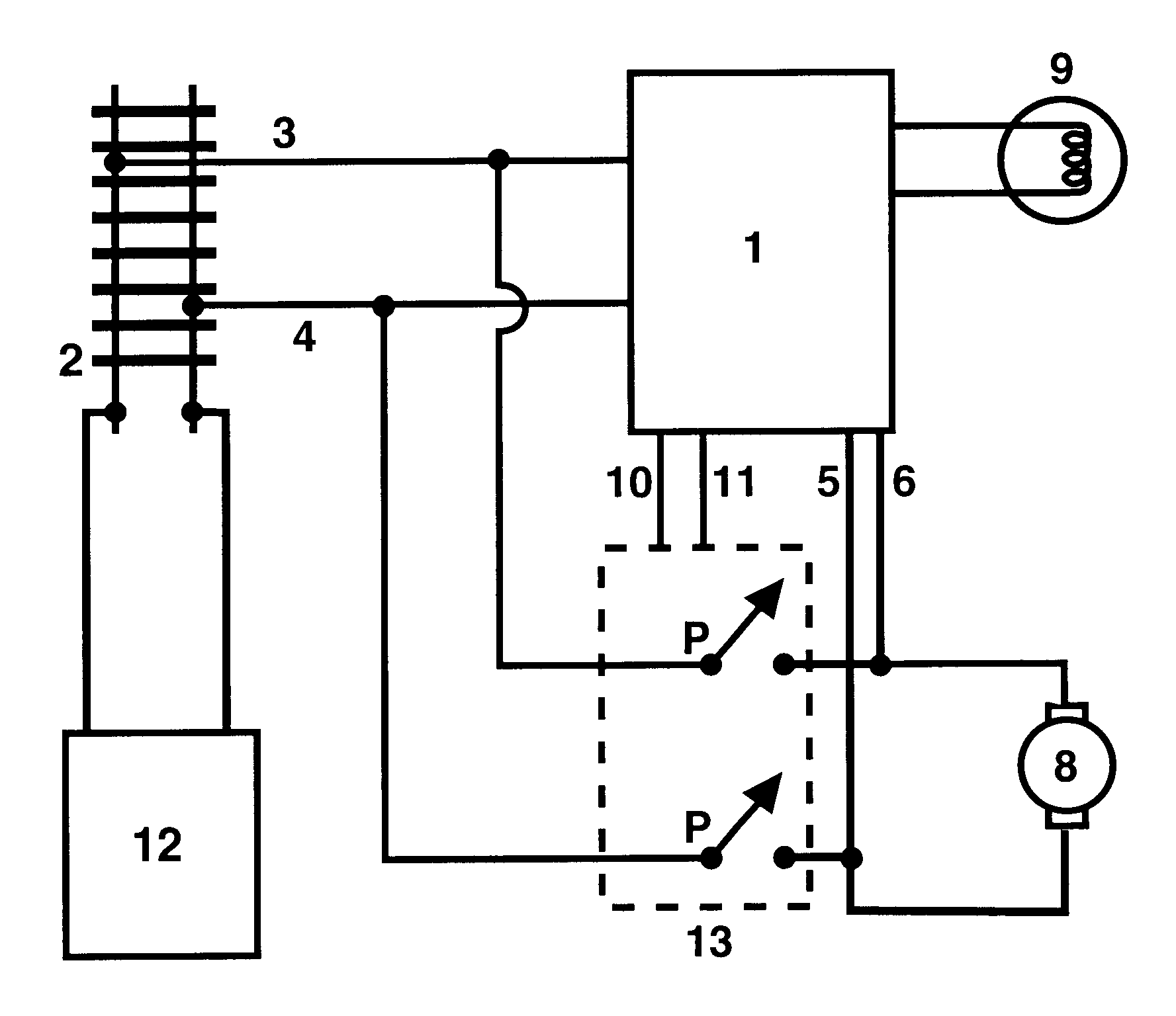
FIG. 2 shows these same elements in the novel configuration employed in the preferred embodiment of this invention.

Item 1 represents the decoder, receiver or electronic control unit that may be used to control the motor, 8, when any track energy supply, 12, connected to the model railroad tracks, 2, provides a compatible and understood control format. The track energy and embedded control information, from 12 via track 2, is conducted by track pickup leads 3 and 4 and conducted to the decoder, 1, and also to a motor current switching arrangement, 7. The track pickup leads 3 and 4, may be via locomotive wheels, track slider shoes, pickup brushes, overhead pantograph pickups or any other conductive method or combination, and may even be via a wired-tether connection.

The motor current switching arrangement, 7, is ...


PUM


Abstract

A method and apparatus to allow compatible speed operations and physical coupling of decoder equipped locomotives to locomotives without decoders when operating on conventional track power. The improvements utilize mechanisms added to improve decoder fault protection, and that can also be usefully additionally employed to allow voltage accurate mode-conversion using a novel, cost reduced and simplified mode-switching arrangement. Additionally, a convenient automation of the mode switching arrangement is shown by using different relay switch configurations controlled by the decoder logic.

Description

BACKGROUND OF INVENTIONThis invention pertains to the field of control systems for scale model railroad layouts, and specifically to improvements in locomotive decoder (receiver) device interface connections and mode-conversion capabilities.The advent of Command Control technologies has led to increased enjoyment and capabilities for model railroaders and their operations of model railroad layouts. Since the early Carrier Control systems of the 1970's and up to the latest Digital Command Control technologies, the key capability of all the technologies is the same. This is the ability to control multiple independently addressed locomotives in the same electrical section of model railroad tracks. All the technologies that communicate these addressed commands to a particular receiver, or decoder, in the locomotive by electrical conduction via the rails employ some variant of encoded time-varying voltage waveforms, and are termed Command Control systems. Additionally, some 1990's prior ...

Claims


Application Information

Patent Timeline
IPC IPC(8): A63H19/24A63H19/00
CPCA63H19/24
Inventor IRELAND, ANTHONY JOHN
Owner IRELAND ANTHONY JOHN
Learn More