Lateral color compensation for projection displays

Inactive Publication Date: 2003-02-04
KONINKLIJKE PHILIPS ELECTRONICS NV
View PDF20 Cites 23 Cited by
  • Summary
  • Abstract
  • Description
  • Claims
  • Application Information

AI Technical Summary

Benefits of technology

A finite pupil position also helps the design of the projection optics in general. Placing the pupil closer to the physical lens assembly is a simpler constraint than the infinite pupil location of a telecentric lens assembly. Providing latitude in specifying the nontelecentric pupil location of projection optics represents a design freedom which tends to simplify the design of projection optics of projection displays of the invention relative to the design of comparable telecentric projection optics. The telecentric condition doe

Problems solved by technology

With increasing demands for higher resolution, higher pixel count, and smaller devices, the difficulty of designing projection lenses for color digital-graphic projection displays has increased.
Such variation in color convergence degrades graphic quality, particularly for projection of computer graphics displays.
Limiting lateral-color misconvergence is a significant issue in the development of three-panel projection monitors.
For example, a projection monitor employing panel arrays having 1200.times.1600 pixels, with each pixel being about 10 microns square, and subject to a design objective of a half pixel or less of lateral-color misconvergence presents a difficult objective for a projection lens maker to achieve.
Lateral-color misconvergence of such magnitude is a significant problem in computer display monitor applications, where icons and menus are typically placed at the edges of the graphic display.
In general, to compensate for lateral color effects, a projection

Method used


Image

  • Lateral color compensation for projection displays
  • Lateral color compensation for projection displays
  • Lateral color compensation for projection displays

Examples


Embodiment Construction

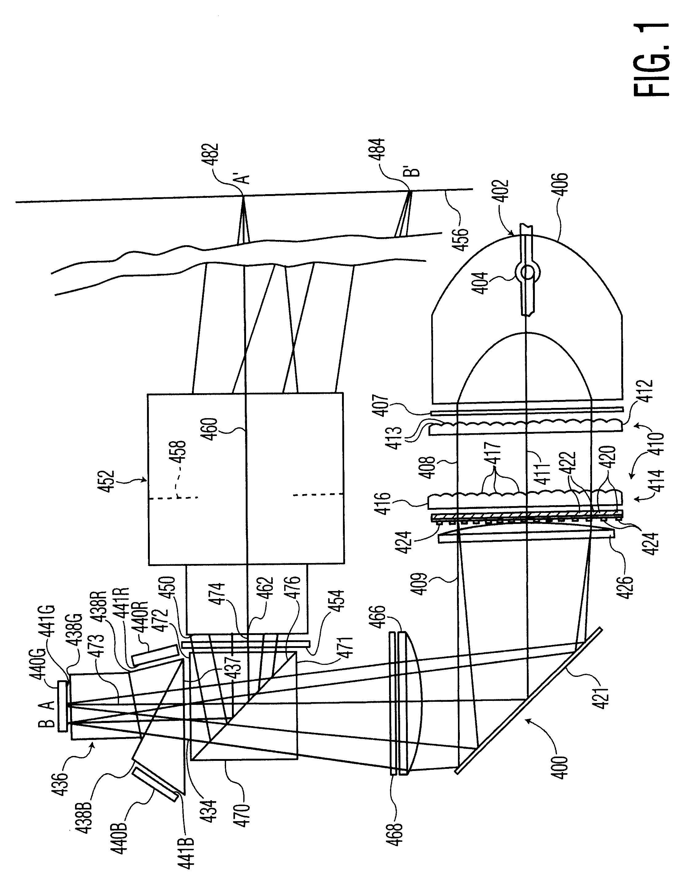
Turning now to FIG. 1, a digital-graphics projection display 400 includes an illumination-beam source assembly 402 which includes a high-intensity lamp 404 and a parabolic reflector 406 which forms an illumination beam 408 of unpolarized white-spectrum light for the projector. An ultraviolet, infrared, and spectral notch filter assembly 407 is placed in the path of the unpolarized illumination beam 408 to remove light of ultraviolet and infrared frequencies from the beam and to impart a desired color spectral shape to the frequency spectrum of the beam.

A light-conserving beam-polarizer assembly 410 is located in the path of the unpolarized illumination beam 408 in the digital-image projector 400. The beam-polarizer assembly 410 is of a type broadly similar to a beam polarizer described in U.S. Pat. No. 5,986,809 to Itoh and Hashizume, the disclosure of which is hereby incorporated by reference. Briefly, the beam-polarizer assembly 410 includes a first lens array 412 consisting of a ...


PUM


Abstract

Compensation of lateral-color chromatic-aberration effects in a digital color-graphics projection display is achieved by providing projection optics for the projection display which is nontelecentric to a certain degree to establish an angled geometry for gathering light off axis for projection by the projection optics and by providing a plurality of component-primary-color object planes for object digital graphics of different primary colors to be projectively displayed through the projection optics. At least two of the component-primary-color object planes are located at different effective axial distances from the projection optics. The effective axial distances of the object planes from the projection optics are respectively keyed to the angled nature of the off-axis light gathering of the projection optics and to the lateral-color chromatic-aberration differences in lateral magnification by the projection optics at different primary colors so that such color-dependent differences in lateral magnification tend to be compensated.

Description

The invention relates broadly to color digital-graphics projection displays based on primary color digital-graphic-encoding beam modulator panels and projection optics for such projection displays. More particularly, the invention relates to such color digital graphics projection displays and projection optics providing compensation for a lateral color chromatic aberration.BACKGROUND ART AND SUMMARY OF THE INVENTIONA typical color digital-graphics projection display arrangement uses three digital-graphic-encoding beam modulator panels, one for each of a red, a green, and a blue component of a color graphic. Examples of beam modulator panels include transmissive polysilicon liquid crystal displays (LCDs), reflective digital micromirror devices (DMDs), and reflective liquid crystal displays (RLCDs)--also known as reflective liquid crystal on silicon displays (LCoS). Often graphic-encoded beams from the three panels are combined optically with component-color beam recombination optics ...

Claims


Application Information

Patent Timeline
IPC IPC(8): G02B27/14G02B27/00H04N9/31G02B27/18G03B21/00
CPCG02B27/0025G02B27/1026G02B27/145H04N9/3197H04N9/3167H04N9/317H04N9/3191H04N9/3105H04N9/31
Inventor SHIMIZU, JEFFREY A.
Owner KONINKLIJKE PHILIPS ELECTRONICS NV
Why Eureka
Try Eureka