Motion control systems

a technology of motion control and control system, applied in the field of motion control system, can solve the problems of high hardware dependence of programs, custom applications, and development by other software developers, and achieve the effect of reducing time and effor

Inactive Publication Date: 2003-02-04
AUTOMATION MIDDLEWARE SOLUTIONS
View PDF65 Cites 57 Cited by
  • Summary
  • Abstract
  • Description
  • Claims
  • Application Information

AI Technical Summary

Benefits of technology

Therefore, the driver stub module 36 allows the motion control system designer to use, with minimal time and effort by the hardware designer, a working software driver 28 that contains driver code to im

Problems solved by technology

While such low level programs offer the programmer substantially complete control over the hardware, these programs are highly hardware dependent.
Custom applications, developed by other software developers, cannot be developed to take advantage of the simple motion control functionality offered by the factory automation program.
Additionally, these programs do not allow the programmer a great degree of control over the each motion control device i

Method used


Image

  • Motion control systems
  • Motion control systems
  • Motion control systems

Examples


example 2

The second example illustrates how the language driver 44 might deal with the Driver function IXMC_DrvExt_Test::SetVelocity.

example 3

The third example illustrates how the language driver 44 might deal with the Driver function

example 4

The fourth example illustrates how the language driver 44 might deal with the Driver function IXMC_DrvExt_Test::Reset.

While the language driver 44 is of particular importance in the context of the software system 22 described above, this technology may have broader application to any hardware in which ASCII strings are employed to transmit commands to and receive responses from hardware.

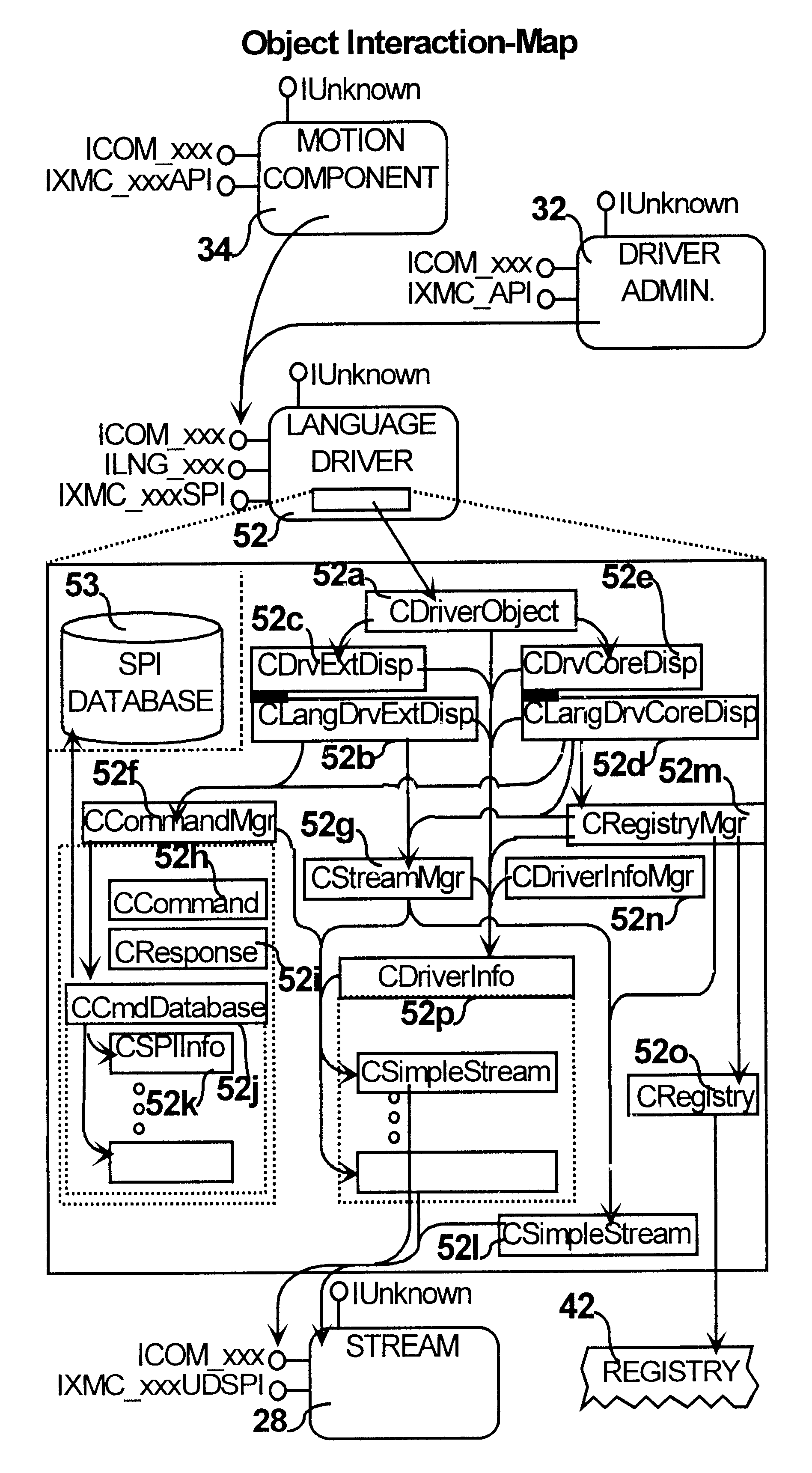
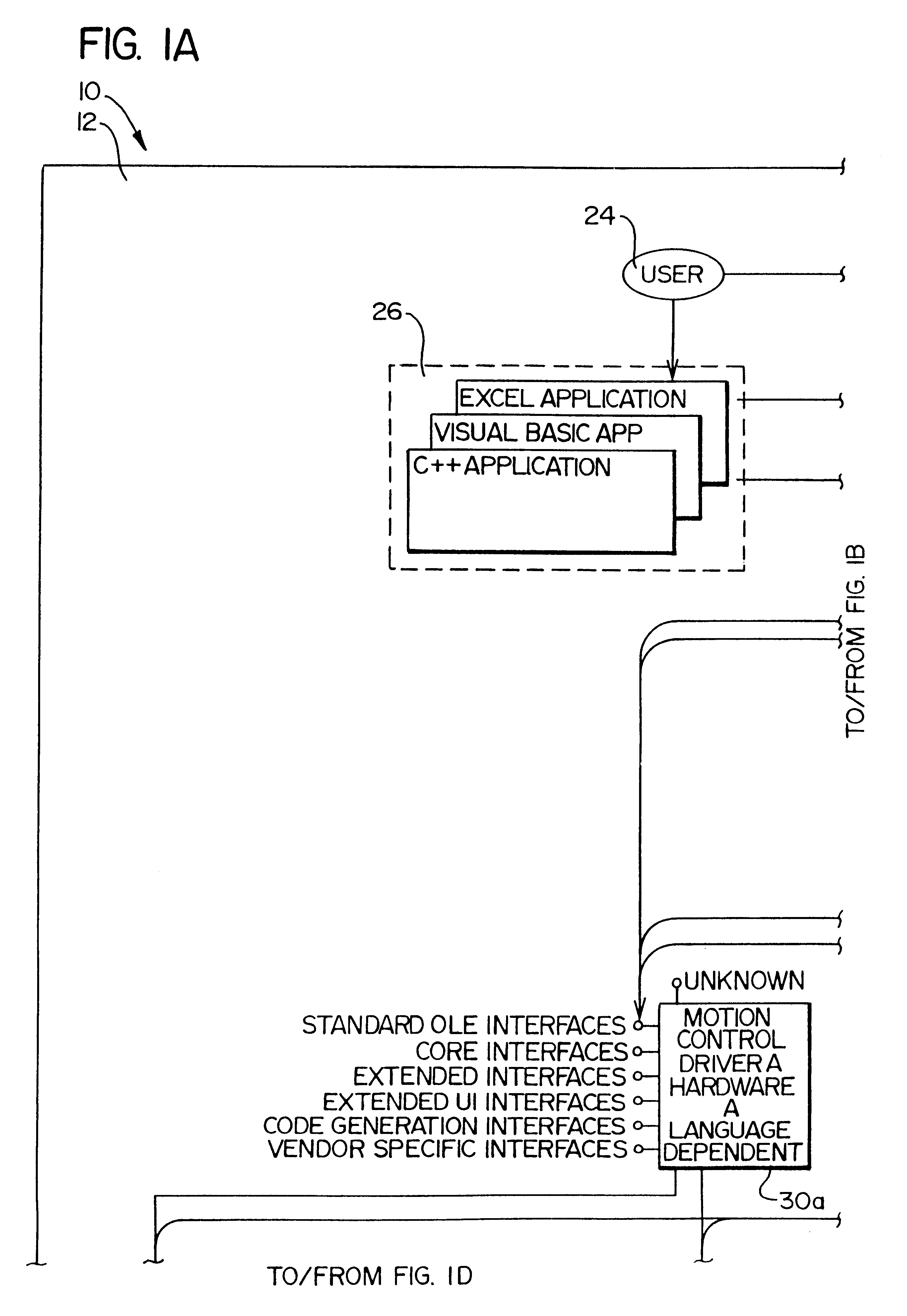
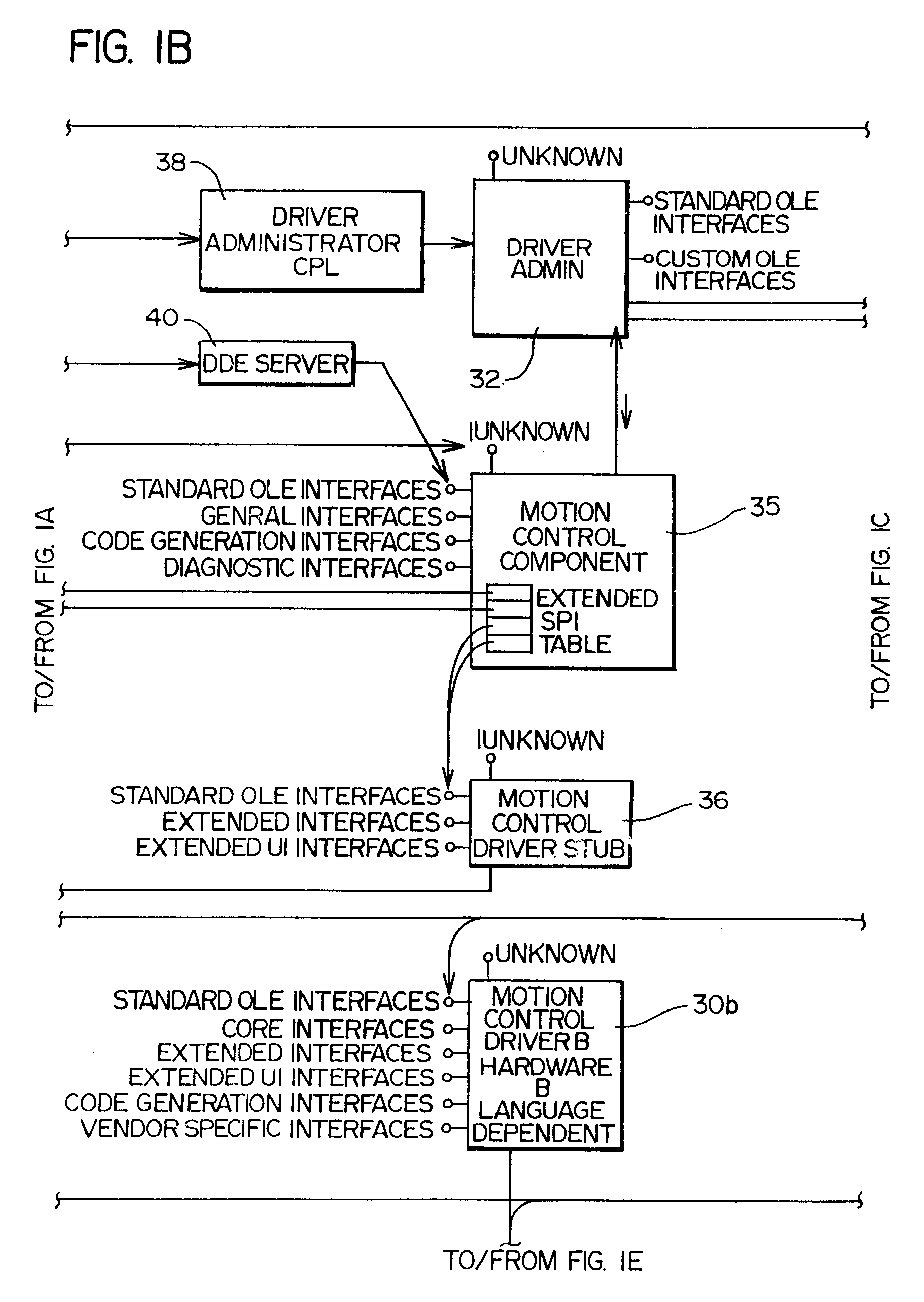
The language driver 44 will now be described in more detail. The language driver 44 is used by both the driver administration 32 and the motion control component 35. Its main purpose is to implement functionality that generates motion control commands for the specific hardware supported.

For example, the AT6400 driver used to control the Compumotor AT6400 motion control hardware, generates AT6400 command codes. During the initialization phase of the system 22, the driver administrator 32 communicates with each language driver 44, allowing the user to add, remove, or change the configuration of the dri...


PUM


Abstract

A system for motion control in which an application is developed that is independent from the actual motion control hardware used to implement the system. The system comprises a software system that employs an application programming interface comprising component functions and a service provider interface comprising driver functions. A system programmer writes an application that calls the component functions. Code associated with the component functions relates these functions to the driver functions. A hardware designer writes driver code that implements the driver functions on a given motion control hardware product. The driver functions are separated into core and extended driver functions. All software drivers implement the core driver functions, while the software drivers need not contain code for implementing the extended driver functions. If the software driver does not contain code to implement an extended driver function, the functionality of the extended driver function is obtained through a combination of core driver functions. The system programmer may also select one or more streams that allow the control commands to be communicated to, and response data to be communicated from, motion control hardware.

Description

The present invention relates to motion control systems and, more particularly, to interface software that facilitates the creation of hardware independent motion control software.1. Background of the InventionThe purpose of a motion control device is to move an object in a desired manner. The basic components of a motion control device are a controller and a mechanical system. The mechanical system translates signals generated by the controller into movement of an object.While the mechanical system commonly comprises a drive and an electrical motor, a number of other systems, such as hydraulic or vibrational systems, can be used to cause movement of an object based on a control signal. Additionally, it is possible for a motion control device to comprise a plurality of drives and motors to allow multi-axis control of the movement of the object.The present invention is of particular importance in the context of a mechanical system including at least one drive and electrical motor hav...

Claims


Application Information

Patent Timeline
IPC IPC(8): G05B19/18G05B19/05G05B15/02G05B19/414G05B19/4155G05B19/416G06F9/06G06F9/445
CPCG05B19/19G05B19/416G05B2219/23262G05B2219/23265G05B2219/34208G05B2219/43167G05B2219/34263G05B2219/34287G05B2219/36035G05B2219/36036G05B2219/36037G05B2219/34216Y02P90/02
Inventor BROWN, DAVID W.CLARK, JAY S.
Owner AUTOMATION MIDDLEWARE SOLUTIONS
Why Eureka
Try Eureka