Multi-stage particulate matter collector

a particulate matter collector and multi-stage technology, applied in the field of multi-stage particulate matter collectors, can solve the problems of unacceptably high pressure drop and outlet particulate emissions, require significant space, and cost a lot of construction

Inactive Publication Date: 2003-02-25
KRIGMONT HENRY V
View PDF19 Cites 38 Cited by
  • Summary
  • Abstract
  • Description
  • Claims
  • Application Information

AI Technical Summary

Problems solved by technology

The disadvantage of this design is that it is entirely electrostatic allowing some of the particulate matter to make it past all the electrodes without being collected, especially in the case of high and/or low resistance dust.
However, because of their low filtration velocities, they are large, require significant space, are costly to build, and unattractive as replacements for existing precipitators.
Reducing their size by increasing the filtration velocity across the filter bags results in unacceptably high pressure drops and outlet particulate emissions.
Th

Method used


Image

  • Multi-stage particulate matter collector
  • Multi-stage particulate matter collector
  • Multi-stage particulate matter collector

Examples


Embodiment Construction

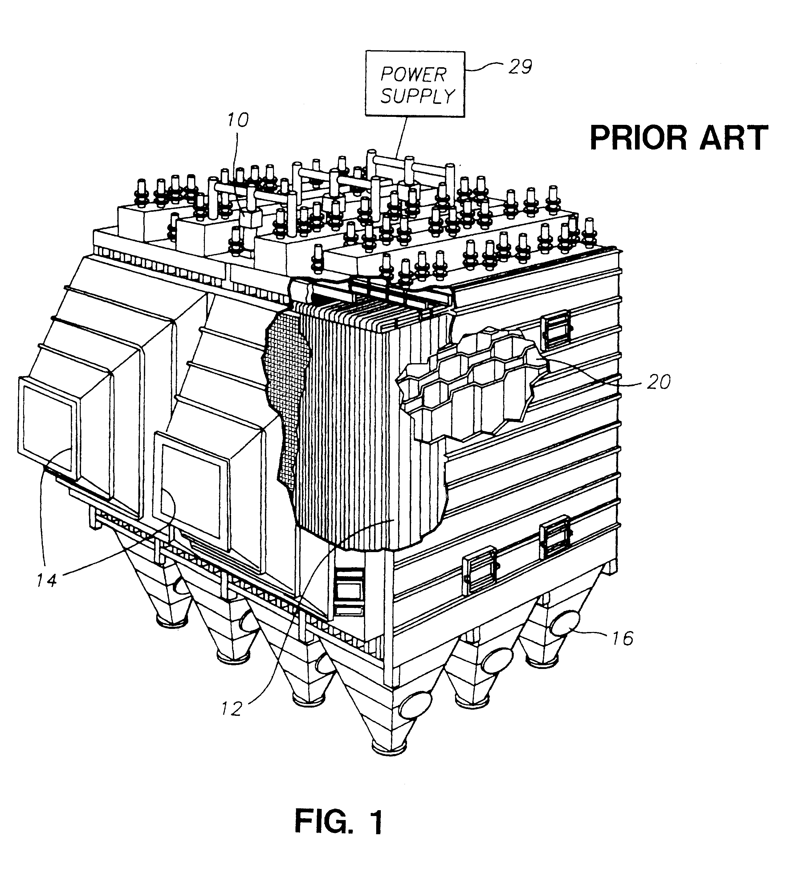
Turning to FIG. 1, a prior art electrostatic precipitator is seen. A power supply 29 powers pairs of corrugated plates separated to form zones. Effluent gas enters the assembly from ports on the side 14 and passes through exiting on the other side (not shown). When the plates are rapped to clean, the collected dust falls to hoppers in the bottom where it can be removed 16. The array assembly 12 shown in detail in 20 is simply the plate corrugations of the alternately positive and negatively charged plates.

The present invention can be fitted into a similar assembly as that shown in FIG. 1 as will be described.

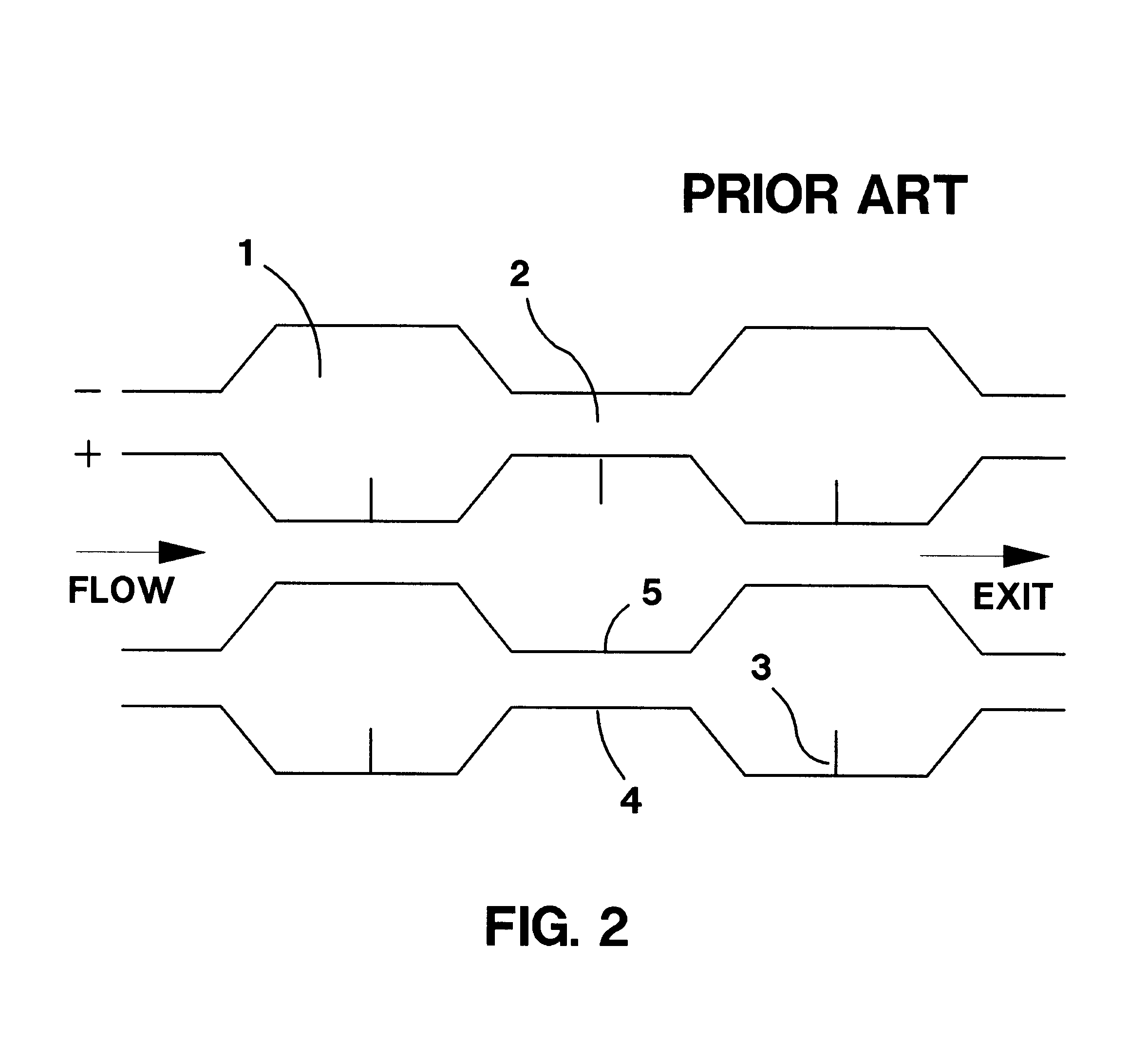
FIG. 2 shows a pair of the corrugated plates 4, 5 from the prior art assembly of FIG. 1. Wide 1 and narrow 2 zones are seen. Electrodes 3 are attached to one of the plates and located in the wide zones 1 to produce a corona discharge.

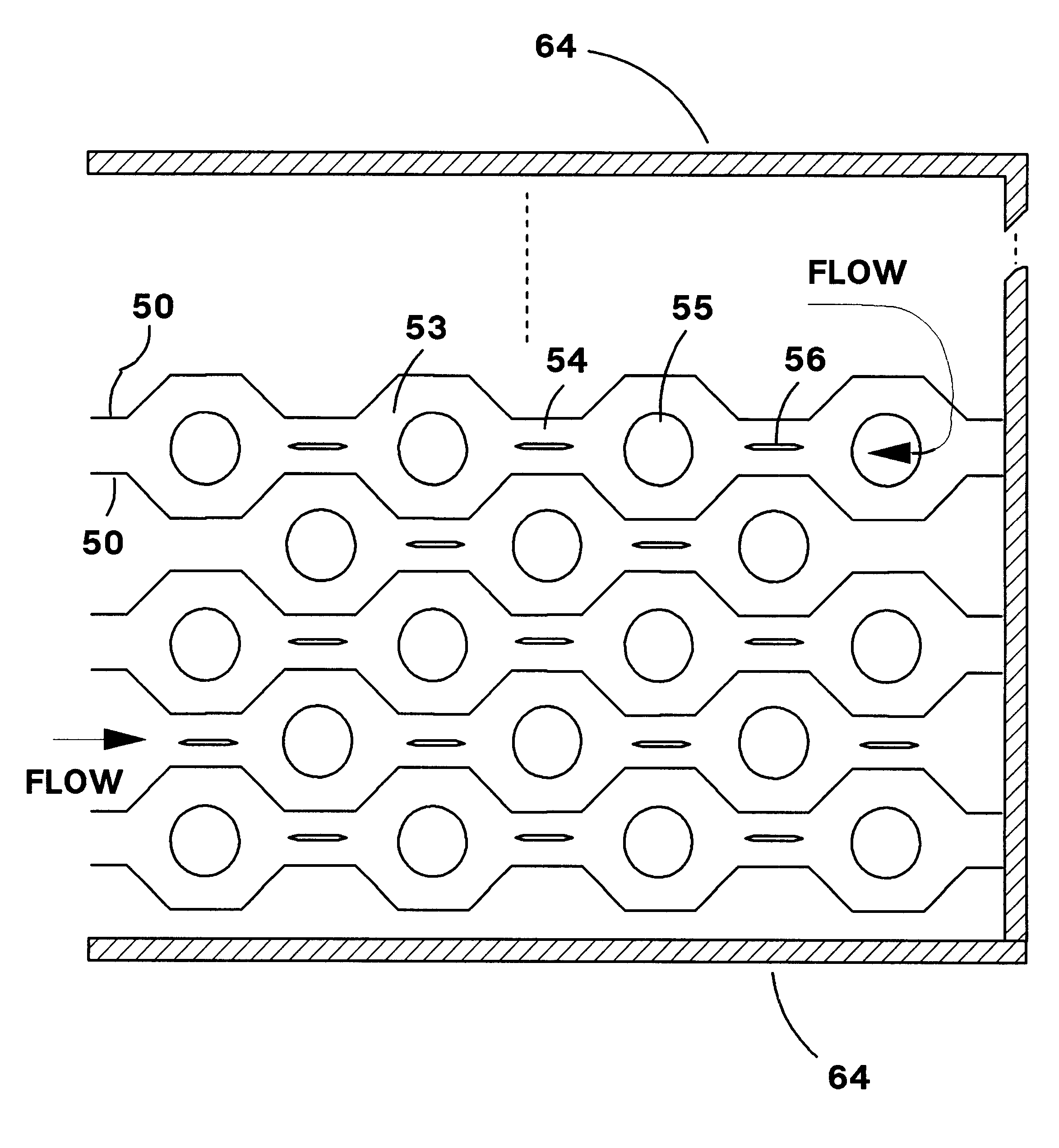
FIG. 3 shows an array that forms an embodiment of the present invention. A plurality of corrugated plate electrodes 50 form cells containing wide z...


PUM

PropertyMeasurementUnit
Electric field strengthaaaaaaaaaa
Electric fieldaaaaaaaaaa

Abstract

A multi-stage particulate matter collector of the type used to collect particles from waste industrial gas. The collector can contain multiple narrow and wide zones formed by a plurality of parallel corrugated plates. Contained in the narrow zones are elongated electrodes with sharp leading and/or trailing edges. These electrodes provide a non-uniform electric field near their sharp edges leading to corona discharge. The corona discharge causes particulate matter in the gas flow to become charged. The region in narrow zones away from the sharp edges of the electrodes resembles a parallel plate capacitor with relatively uniform electric field. In this region, particles can be collected on the plates and on the electrode. Wide regions can contain barrier filters (bag filters) with conductive surfaces. The electric field is also relatively uniform in this region causing electrostatic collection on the plates and filter surface. Gas exits the array through the sides of the barrier filters which provides additional highly efficient filtering.

Description

1. Field of the InventionThis invention relates generally to the field of particulate matter collection from discharge gases and more particularly to a multi-stage particulate matter collector that collects both electrostatically and with barrier filters.2. Description of Related ArtIt is well known in the art how to build and use electro-static precipitators. It is also known how to build and use a barrier filter such as a baghouse. Further, it is known how to charge particles so that these charged particles may be collected in a barrier filter with lower pressure drop and emissions than uncharged particles collected at the same filtration velocity.Prior art designs have been discussed in the U.S. Pat. No. 5,547,493 (Krigmont), U.S. Pat. No. 5,938,818 (Miller), U.S. Pat. No. 5,158,580 (Chang), and U.S. Pat. No. 5,024,681 (Chang). Krigmont teaches a new precipitator electrode design / configuration, while the Miller and Chang deal with a combination of a precipitator or electrostatic ...

Claims


Application Information

Patent Timeline
IPC IPC(8): B03C3/08B03C3/04B03C3/38B03C3/66B03C3/34B03C3/36
CPCB03C3/08B03C3/66B03C3/38B03C3/36
Inventor KRIGMONT, HENRY V.
Owner KRIGMONT HENRY V
Why Eureka
Try Eureka