Method for making cardiac leads with zone insulated electrodes

a technology of electrodes and electrodes, applied in the field of cardiac stimulator leads, can solve the problems of limited power consumption efficiency, limited miniaturization of ring-type electrodes, and high cost of power consumption

a technology of electrodes and electrodes, applied in the field of cardiac stimulator leads, can solve the problems of limited power consumption efficiency, limited miniaturization of ring-type electrodes, and high cost of power consumption

US6526321B1Inactive Publication Date: 2003-02-25INTERMEDICS

Image

  • Method for making cardiac leads with zone insulated electrodes
  • Method for making cardiac leads with zone insulated electrodes
  • Method for making cardiac leads with zone insulated electrodes

Examples


Embodiment Construction

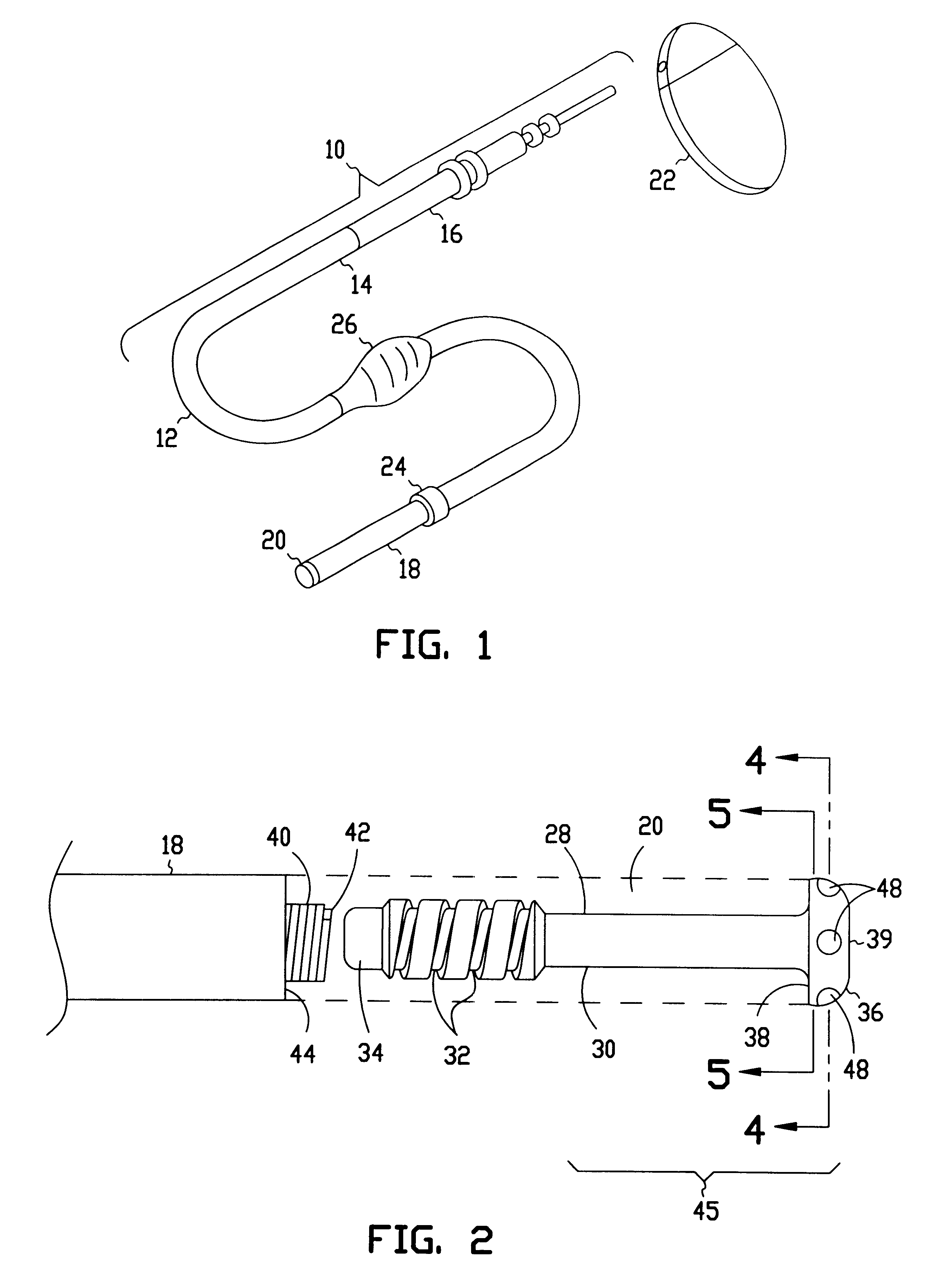
In the drawings described below, reference numerals are generally repeated where identical elements appear in more than one figure. Turning now to the drawings, and in particular to FIG. 1, there is shown an exemplary cardiac stimulator lead 10 that includes a flexible insulating sleeve 12 that has a proximal end 14 coupled to a connector 16, and a distal end 18 coupled to a tip electrode 20. The connector 16 is designed to be inserted into a cardiac stimulator 22, and is shown highly exaggerated in size relative to the cardiac stimulator 22. The cardiac stimulator 22 may be a pacemaker, a cardioverter / defibrillator, or other type of stimulator or a sensing instrument. The illustrated embodiment of the lead 10 is bipolar. Accordingly, the distal end 18 is provided with an electrode 24 located proximal to the tip electrode 20. However, unipolar or other multi-polar arrangements are possible as well. A suture sleeve 26 is slipped over the sleeve 12. During implantation, the suture sle...


PUM


Abstract

An electrode for a cardiac lead and method of making the same are provided. The electrode includes an electrode member and a coating applied to the electrode member. A method of fabricating a high impedance cardiac lead electrode is provided. The method includes the steps of providing an electrode member and coating a first portion of the electrode member with an electrically insulating material and placing a tubular mask or shield over the electrode. Portions of the insulating material are removed to expose selected areas of the electrode. The second or exposed portion enhances the impedance of the electrode, resulting in power savings and extended life spans for implantable stimulation and sensing devices. Exemplary materials for the coating includes diamond-like carbon and sapphire.

Description

1. Field of the InventionThis invention relates generally to cardiac stimulator leads, and more particularly to a cardiac stimulator lead having an electrode selectively coated with an insulating material to define small conductive regions.2. Description of the Related ArtConventional cardiac stimulator systems consist of a cardiac stimulator and an elongated flexible cardiac lead that is connected proximally to a header structure on the cardiac stimulator and is implanted distally at one or more sites within the heart requiring cardiac stimulation or sensing. The cardiac stimulator is normally a pacemaker, a cardioverter / defibrillator, a sensing instrument, or some combination of these devices.At the time of implantation, the distal end of a cardiac lead is inserted through an incision in the chest and manipulated by the physician to the site requiring electrical stimulation with the aid of a flexible stylet that is removed prior to closure. At the site requiring electrical stimula...

Claims


Application Information

Patent Timeline
25 Feb 2003
Publication
US6526321B1
IPC
A61N1/05
CPC
A61N1/0565
Inventors
SPEHR, PAUL R.