Extrusion process for fabricating plastic optical fiber

a technology of extrusion and plastic, applied in the field of graded index plastic optical fiber fabrication, can solve the problems of insufficient use of optical fiber, insufficient cost effectiveness of glass optical fiber, and insufficient time consumption of optical fiber, etc., and achieve the effects of reducing production costs, reducing labor intensity, and reducing labor intensity

Inactive Publication Date: 2003-03-04
FITEL USA CORP
View PDF14 Cites 35 Cited by
  • Summary
  • Abstract
  • Description
  • Claims
  • Application Information

AI Technical Summary

Problems solved by technology

Such optical fiber has not found significant usage, however, in smaller scale applications, such as distribution of fiber to the desk in local area networks.
In particular, glass optical fiber has not been as cost effective as, for example, copper wire, and connectorization of glass fiber (which needs well-polished end faces) requires substantial time, skilled personnel, and precise connector components.
Unfortunately, the modes propagating in a step index fiber experience an undesirably high level of dispersion, thereby limiting the fiber's capability.
GI-POF, however, was more difficult, and thus more expensive, to manufacture than step index POF.
Extrusion was expected to be quicker and cheaper than forming and drawing a preform, but the need for a graded refractive index profile created complications.
In particular, it is not clear that the process is able to be performed without providing a delay time (stopping the flow of material) or a very slow extrusion speed, to allow the diffusible material sufficient time to diffuse.
It is unclear whether this small contact distance allows sufficient diffusion, without requiring either intermittent stoppage or an extremely slow extrusion speed.
Unfortunately, the reference does not disclose an extrusion speed nor make clear whether the process had to be halted intermittently.
In addition, there is no information on how to predict the refractive index profile in the resulting fiber, and trial-and-error is apparently required to find appropriate process parameters.
Specifically, it was discovered that conventional extrusion techniques, e.g., screw extruders, tended to introduce an undesirable amount of particulate contaminants which increased the loss of the drawn fiber.
As noted above, particulate contamination from various moving parts tends to contribute to degradation of the properties of the drawn fiber.
A potential problem with using gas pressure to drive extrusion is the possibility that the gas will be absorbed into the polymer, and thereby induce bubble formation in the drawn fiber.

Method used


Image

  • Extrusion process for fabricating plastic optical fiber
  • Extrusion process for fabricating plastic optical fiber
  • Extrusion process for fabricating plastic optical fiber

Examples


Embodiment Construction

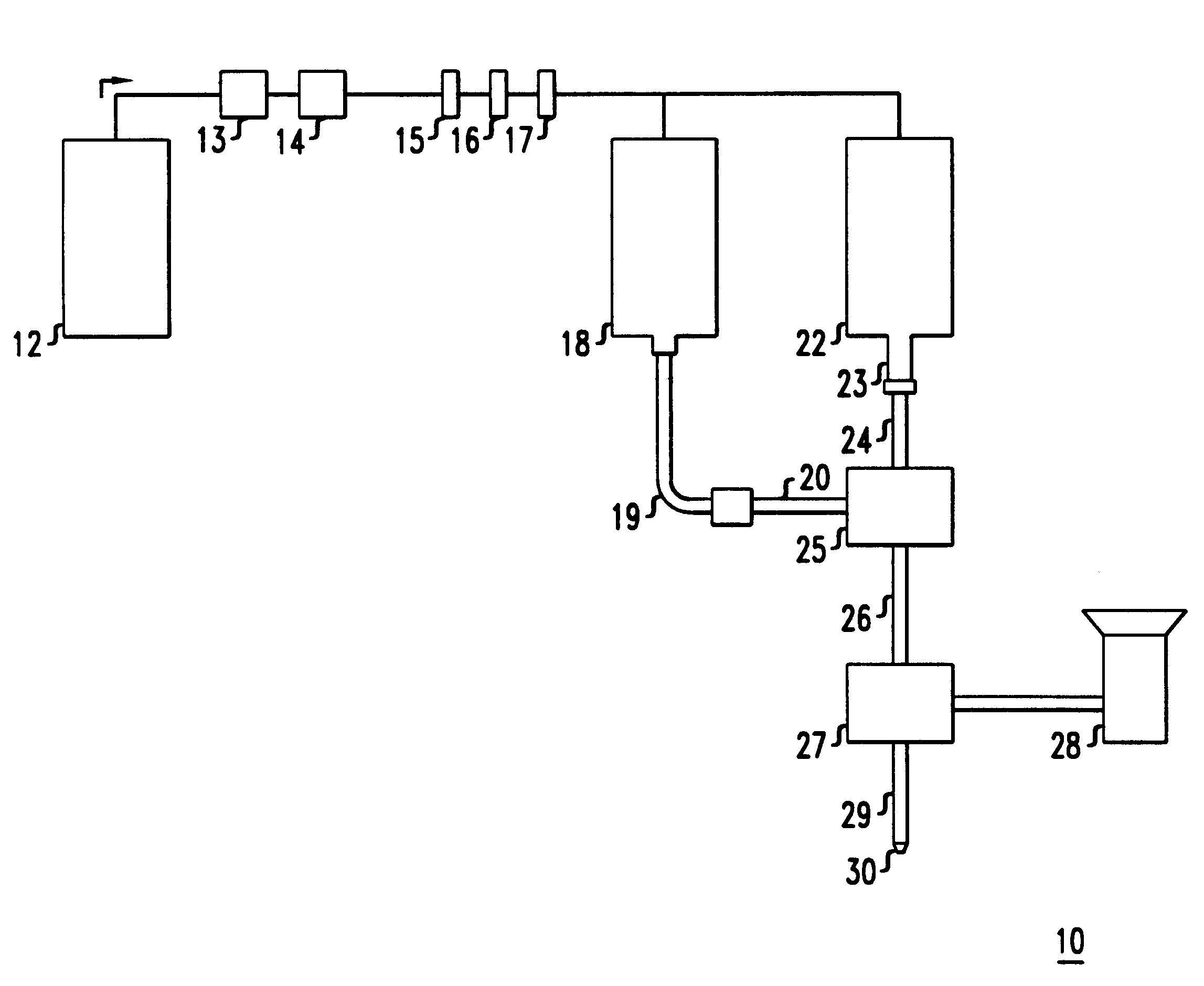
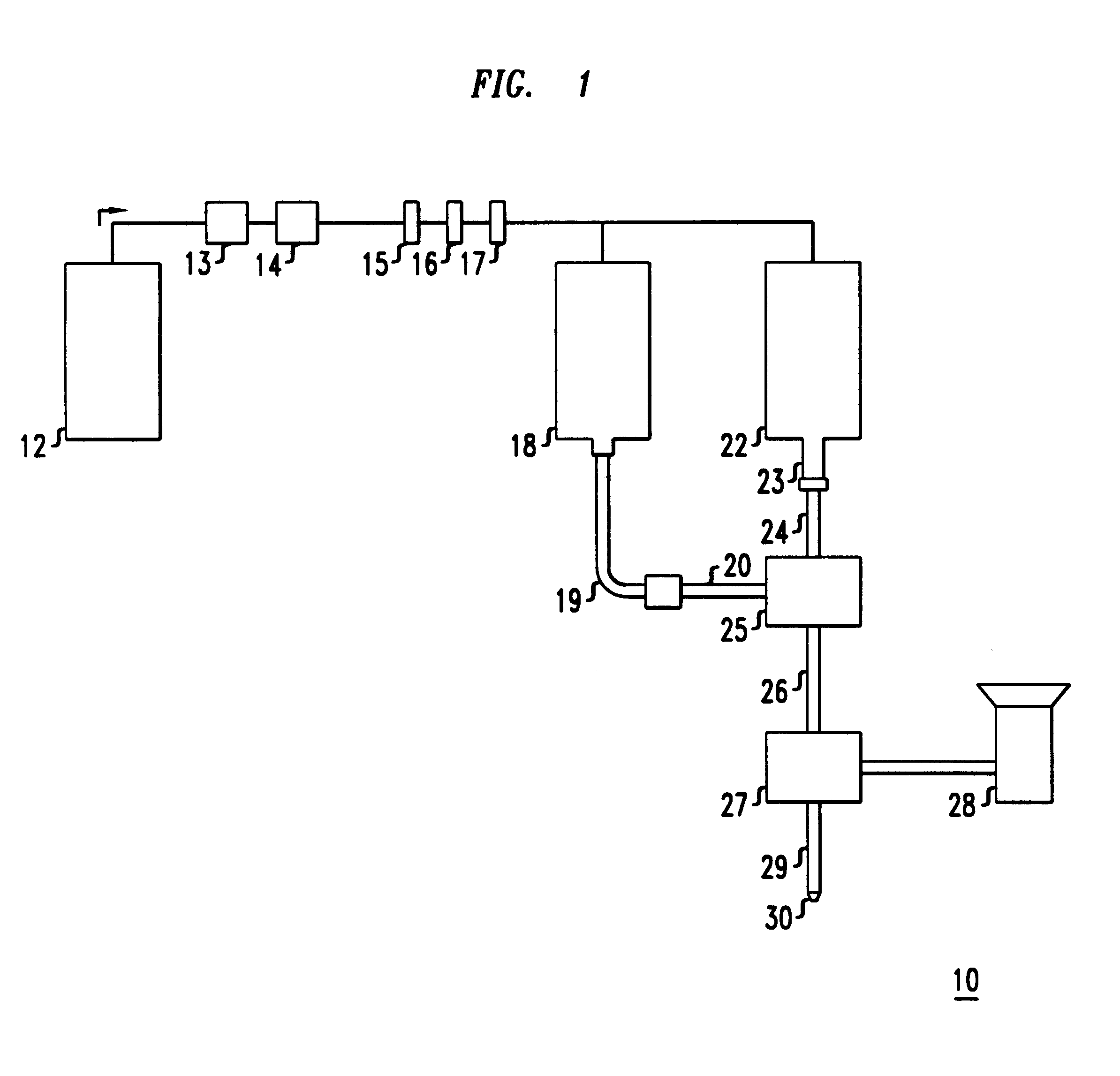
The apparatus set-up is similar to that illustrated in FIG. 1.

Gas pressure to the core and cladding reservoirs was provided by nitrogen gas, the nitrogen gas source at a pressure of about 2400 psi. Before reaching the reservoirs, the gas flowed through two high pressure regulators to control the pressure delivered to the reservoirs, and then through three filters--a 1 .mu.m filter, a 0.01 .mu.m filter, and another 1 .mu.m filter.

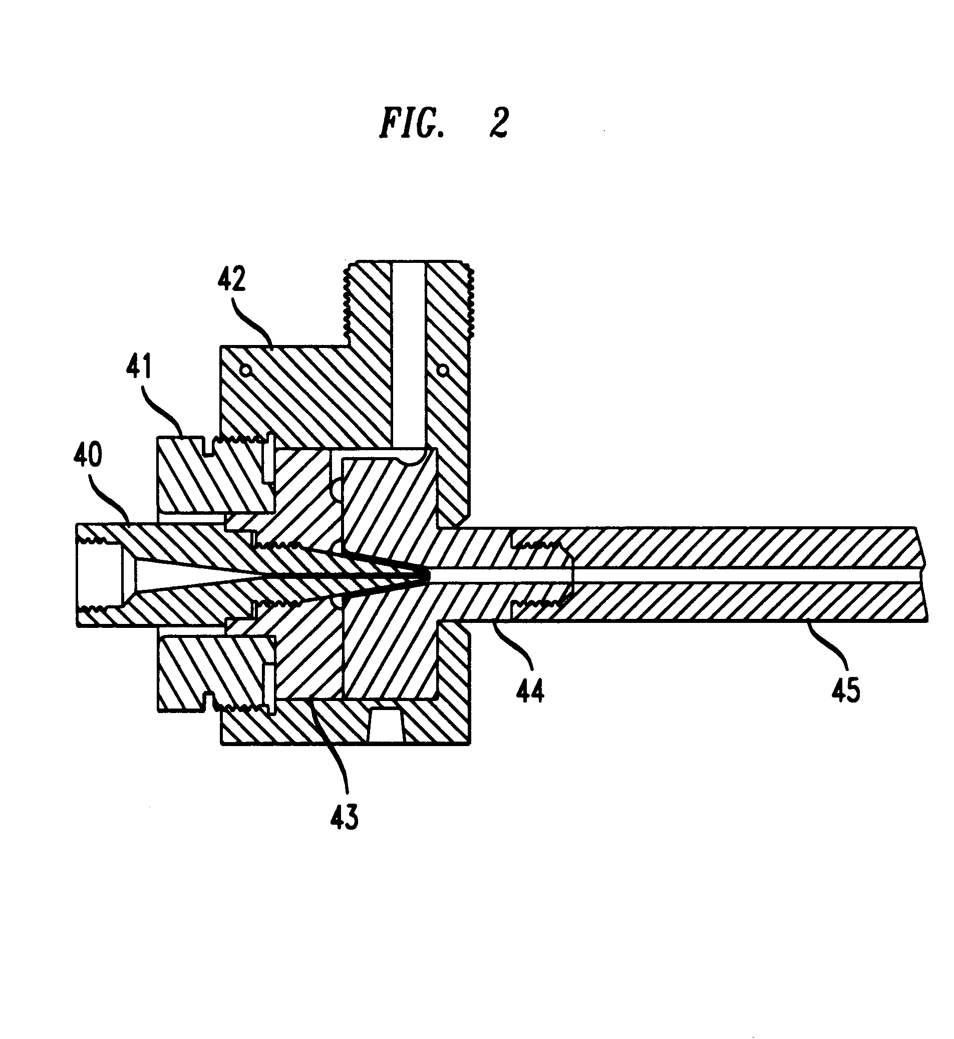
The cylindrical core reservoir, 24 inches in length with an inner diameter of 1.374 inches, was connected through a tapered adapter to a flow restrictor assembly, which in turn was connected through an adapter to a crosshead of the design shown in FIG. 2. The flow restrictor assembly consisted of the thermal homogenizer--a 3.97 inches long nickel tube having an inner diameter of 0.245 inches and the flow restrictor--a 5 inches long nickel tube having an inner diameter of 0.055 inches. The connections between the tubes and between the tubes and the adapters w...


PUM

PropertyMeasurementUnit
distanceaaaaaaaaaa
inner diameteraaaaaaaaaa
temperatureaaaaaaaaaa

Abstract

An improved process for extruding plastic optical fiber without the need to prepare a preform is provided. Specifically, it was discovered that conventional extrusion techniques, e.g., screw extruders, tended to introduce an undesirable amount of particulate contaminants which increased the loss of the drawn fiber. To overcome this problem, the invention substantially reduces the number of mechanical interactions that contribute to such contamination. The process of the invention does so by using fluid pressure, instead of, e.g., screw extruders, to induce polymer flow. The process also controls the flow characteristics of the polymer, or halts the flow altogether, without mechanical controls. Specifically, the temperature of the sections through which the polymer flows is controllably adjusted, such that it is possible to bring the polymer to a desired flow rate or even to a solid state to provide a plug.

Description

1. Field of the InventionThe invention relates to fabrication of graded-index plastic optical fiber.2. Discussion of the Related ArtGlass optical fiber has become a significant transmission medium in recent years, particularly for long distance transmission applications. Such optical fiber has not found significant usage, however, in smaller scale applications, such as distribution of fiber to the desk in local area networks. In particular, glass optical fiber has not been as cost effective as, for example, copper wire, and connectorization of glass fiber (which needs well-polished end faces) requires substantial time, skilled personnel, and precise connector components. There has been interest, therefore, in pursuing plastic optical fiber (POF). POF offers many of the benefits of glass optical fiber, but is expected to be more cost effective, and POF also offers a larger core that makes connection easier.Initially, step index POF (having a core of one refractive index, surrounded b...

Claims


Application Information

Patent Timeline
Patent Type & Authority Patents(United States)
IPC IPC(8): B29C47/20B29C47/28B29C47/36B29D11/00B29C48/05B29C48/34B29C48/36
CPCB29C47/28B29D11/00663B29C47/36B29C47/0014B29L2011/0075B29C48/30B29C48/05B29C48/34B29C48/36B29D11/00682
Inventor BLYLER, JR., LEE L.HART, JR., ARTHUR CLIFFORDRATNAGIRI, RAMABHADRAWHITE, WHITNEY
Owner FITEL USA CORP
Why Eureka
Try Eureka