Method and device for the improvement of the pose accuracy of effectors on mechanisms and for the measurement of objects in a workspace

a technology of effectors and pose accuracy, applied in the field of methods, can solve the problems of inexact system, inability to identify the position of lasers or tools relative to the root of the hand, and inability to derive an absolute size standard of the robo

Inactive Publication Date: 2003-03-04
KNOLL ALOIS +1
View PDF8 Cites 63 Cited by
  • Summary
  • Abstract
  • Description
  • Claims
  • Application Information

AI Technical Summary

Problems solved by technology

Problematical is the fact that, using a laser beam, it is not possible to identify the position of the laser or the tool relative to the root of the hand completely.
Moreover, the system is inexact due to the distortion of the image of the me

Method used


Image

  • Method and device for the improvement of the pose accuracy of effectors on mechanisms and for the measurement of objects in a workspace
  • Method and device for the improvement of the pose accuracy of effectors on mechanisms and for the measurement of objects in a workspace
  • Method and device for the improvement of the pose accuracy of effectors on mechanisms and for the measurement of objects in a workspace

Examples


examples of embodiments

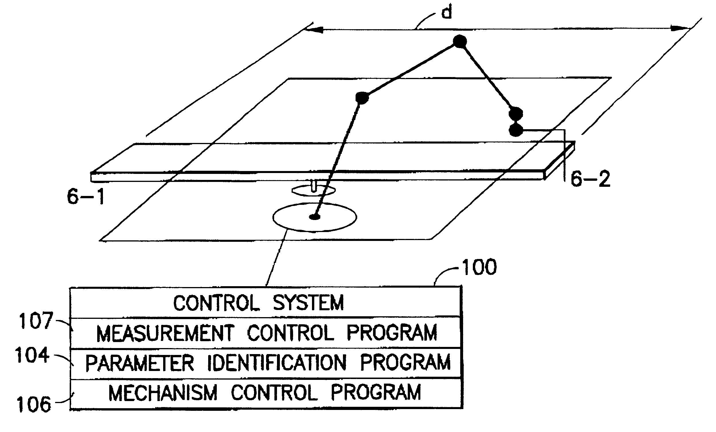
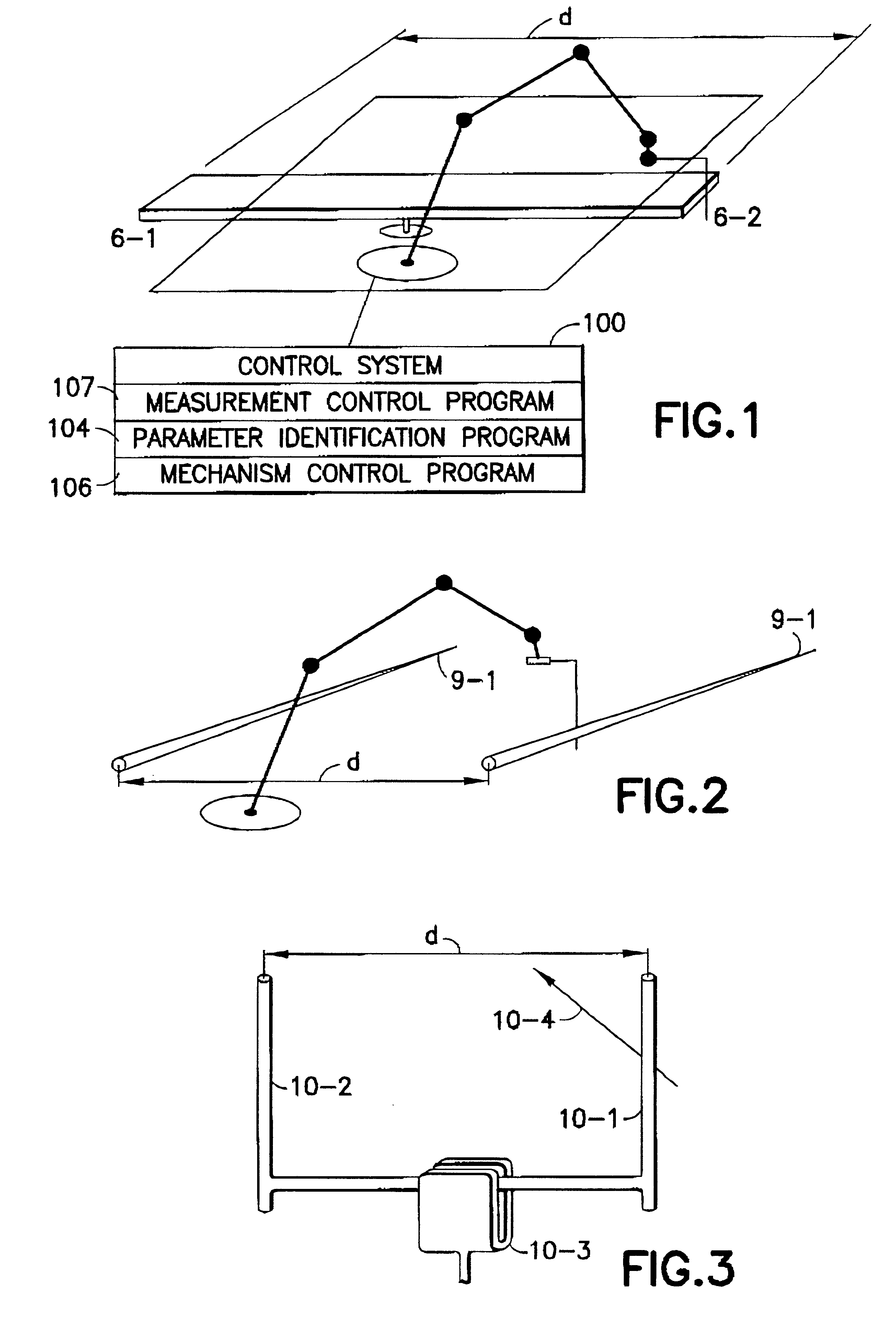
A one-joint measuring mechanism 8-2 in FIG. 21 measures its pose within the workspace in accordance with the invention with increased precision. In this case, an effector object 8-3 is a light plane and reference objects 8-4 on the walls of the cell are point-shaped photo detectors of which the distance between them has to be known. For the purpose of pose measurement, the measuring mechanism will rotate the effector object 8-3 about its only axis and the signals at the reference objects 8-4 are registered in the customary manner and passed on to an associated computer system.

If the light plane has been mounted in such a manner that the joint axis lies on this plane, shifting of the mechanism along this axis must always trigger the same signals. Put differently, shifting the mechanism parallel to the joint axis can under no circumstances be recognised using the methods according to the present invention. Consequently, the light plane must, for the purpose of full measurement, be mou...


PUM


Abstract

A device and a method for measuring the pose of mechanisms includes at least one effector object fixedly joined to a mechanism (e.g., industrial robot, hexapod) in which the at least one effector object moves along one of several axes. The ideal, effective shape of the at least one effector object is a point, a straight line, a plane, an ellipsoid, a cylinder, a hyperboloid or a combination thereof. The movable effector objects interact with reference objects which are arranged in defined positions relative to the mechanism. The interactions are detected by a suitable sensor. The interactions are detected, only the pertaining joint configuration of the mechanism is transmitted to the information processing unit and evaluated and no further continuous values of measuring parameters are required for the evaluation.

Description

1. Field of the InventionThe invention concerns a method and device for improving the pose accuracy of a mechanism having tolerances in a workspace, the mechanism being movable in at least one axis and having an effector, wherein at least one effector object is fixedly mounted on the effector and is eccentric relative to the at least one axis of the mechanism and at least one reference object is arranged in the workspace so that it is fixed relative to the mechanism. A computer system with measurement and control programs is operatively connected to the mechanism. The effector and reference object form a signal trigger / signal detector pair suitable for enabling the triggering and detection of at least binary signals, wherein the totality of the signal poses of the detector relative to the trigger device in which a signal is triggered on the detector may be described by at least one non-trivial characteristic equation.2. Description of the Related ArtA number of methods for improving...

Claims


Application Information

Patent Timeline
IPC IPC(8): B25J9/16B25J9/10G01B11/00B25J9/22G01B21/00G05B19/18G05D1/08
CPCB25J9/1692
Inventor KNOLL, ALOISKOVACS, PETER
Owner KNOLL ALOIS
Why Eureka
Try Eureka