Reducing skin friction drag

a skin friction and drag technology, applied in marine propulsion, machine/engine, vessel construction, etc., can solve the problem of significant constraints in the practicability of scramjet propulsion systems for vehicles travelling at hypersonic speeds, and achieve the effect of reducing skin friction drag

Inactive Publication Date: 2003-03-18
QUEENSLAND UNIV OF
View PDF2 Cites 19 Cited by
  • Summary
  • Abstract
  • Description
  • Claims
  • Application Information

AI Technical Summary

Benefits of technology

It is an object of the present invention to provide a method and apparatus for reduci...

Problems solved by technology

It is known that the skin friction drag is due to the viscosity of air, which causes retardation of that part of the air stream passing around the vehicle and which is adjacent to the surface of the vehicle including both external surfaces of the vehicle and internal surfaces within the sc...

Method used


Image

  • Reducing skin friction drag
  • Reducing skin friction drag
  • Reducing skin friction drag

Examples


Embodiment Construction

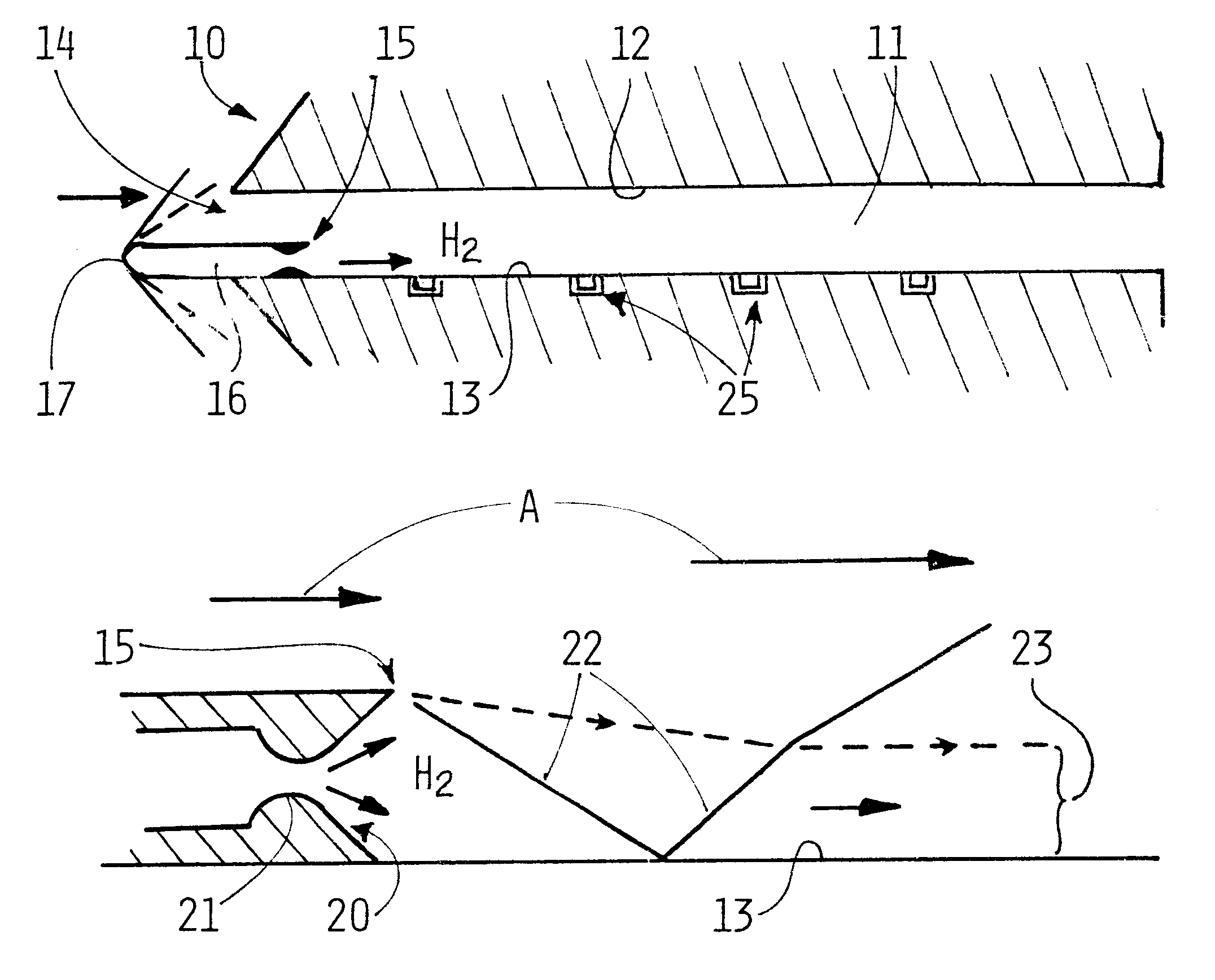
Referring to FIGS. 1 and 2, tests were carried out in a shock tunnel apparatus 10 having an experimental duct 11 having parallel planar upper and lower faces 12, 13. A high speed air flow was introduced into the mouth 14 of the duct 11, the mainstream flow A through the duct 11 being at Mach 4.5, a stagnation enthalpy of 7.8 MJ / kg, a pressure of 50 kPa and a temperature of 1500.degree. K, (this is a combination of flow variables including thermodynamic parameters sufficient to ensure combustion in the boundary layer along duct face 13 as discussed below).

Hydrogen was injected through a rearward facing step 15 formed at the trailing face of an injection strut 16 located on the duct face 13. The leading edge 17 of the strut 16 was located sufficiently far upstream of the mouth 14 to ensure that the shock and succeeding Prandtl-Meyer expansion did not pass into the duct 11.

As better shown in FIG. 2, the step 15 provides a nozzle 20 which forms a slot extending across and parallel to th...


PUM


Abstract

The skin friction drag acting on a surface of an article travelling at high speed such as a vehicle at supersonic or particularly hypersonic speed can be reduced by introducing a fuel into the boundary layer under conditions of the fuel introduction to ensure combustion in the boundary layer. The fuel is injected through orifice(s) or a slot provided at the surface so that the fuel enters the passing fluid with a major component of the direction of injection being parallel to the local flow direction. The fuel is injected at supersonic speed, e.g. at a speed of about Mach 1.5 or higher. The invention is applicable to scramjet engines with the fuel being injected around the entire internal circumference of the wall of the scramjet engine, upstream of the commencement of the combustion chamber.

Description

This invention relates to methods and apparatus for reducing skin friction drag and to systems utilising such methods and apparatus, particularly in the field of reducing the drag force on high velocity vehicles passing through the atmosphere.The invention is particularly suitable for, but not limited to, the reduction of drag in vehicles travelling at high speeds through the atmosphere. Of particular interest are vehicles travelling at hypersonic speeds, i.e. travelling at speeds of about or greater than five times the speed of sound in the atmosphere. However, vehicle travelling at near hypersonic speeds (e.g. between Mach 4 and 5) and at supersonic speeds are also of interest and the invention relates also to such vehicles. When used in this specification, the term "vehicle" is intended to include for example aircraft, space planes, missiles, projectiles and other such flying objects.Presently used propulsion systems for launching satellites into earth orbit use rocket propulsion...

Claims


Application Information

Patent Timeline
IPC IPC(8): F02K7/00F02K7/14
CPCF02K7/14
Inventor GOYNE, CHRISTOPHER PAULSTALKER, RAYMOND JOHNPAULL, ALLAN
Owner QUEENSLAND UNIV OF
Why Eureka
Try Eureka