Bell and hopper for shaft furnaces

Inactive Publication Date: 2003-04-01
PAUL WURTH SA
View PDF9 Cites 11 Cited by
  • Summary
  • Abstract
  • Description
  • Claims
  • Application Information

AI Technical Summary

Problems solved by technology

This entrainment of the tilting drive on the rotating chute carrier of the bell and hopper exhibits in the practical embodiment the disadvantage that a complex, expensive, and failure-prone energy transmission onto the rotating part is required, for example, by slip rings.
The drive means are less easily accessible; however, the employ

Method used


Image

  • Bell and hopper for shaft furnaces
  • Bell and hopper for shaft furnaces
  • Bell and hopper for shaft furnaces

Examples


Embodiment Construction

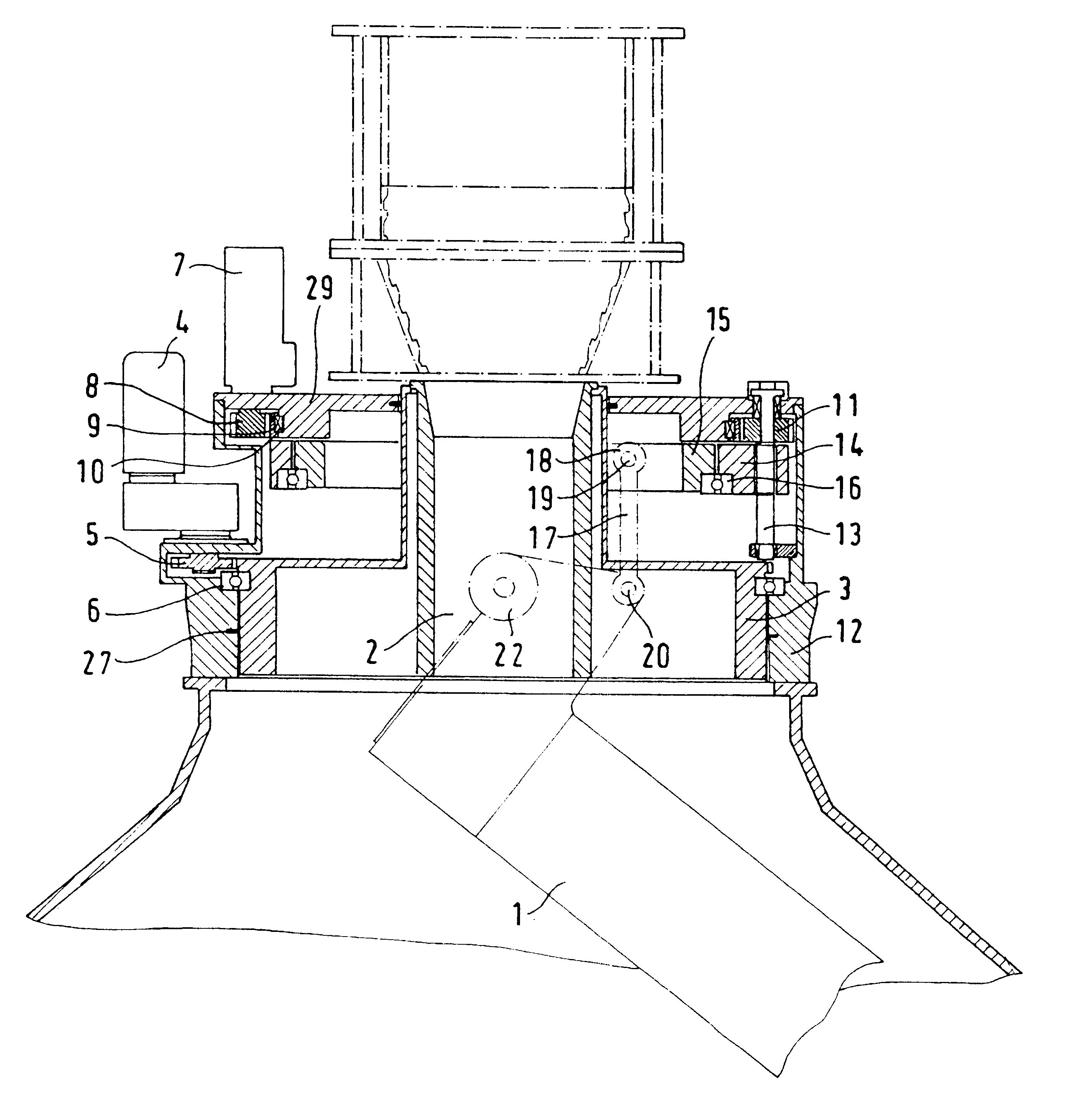
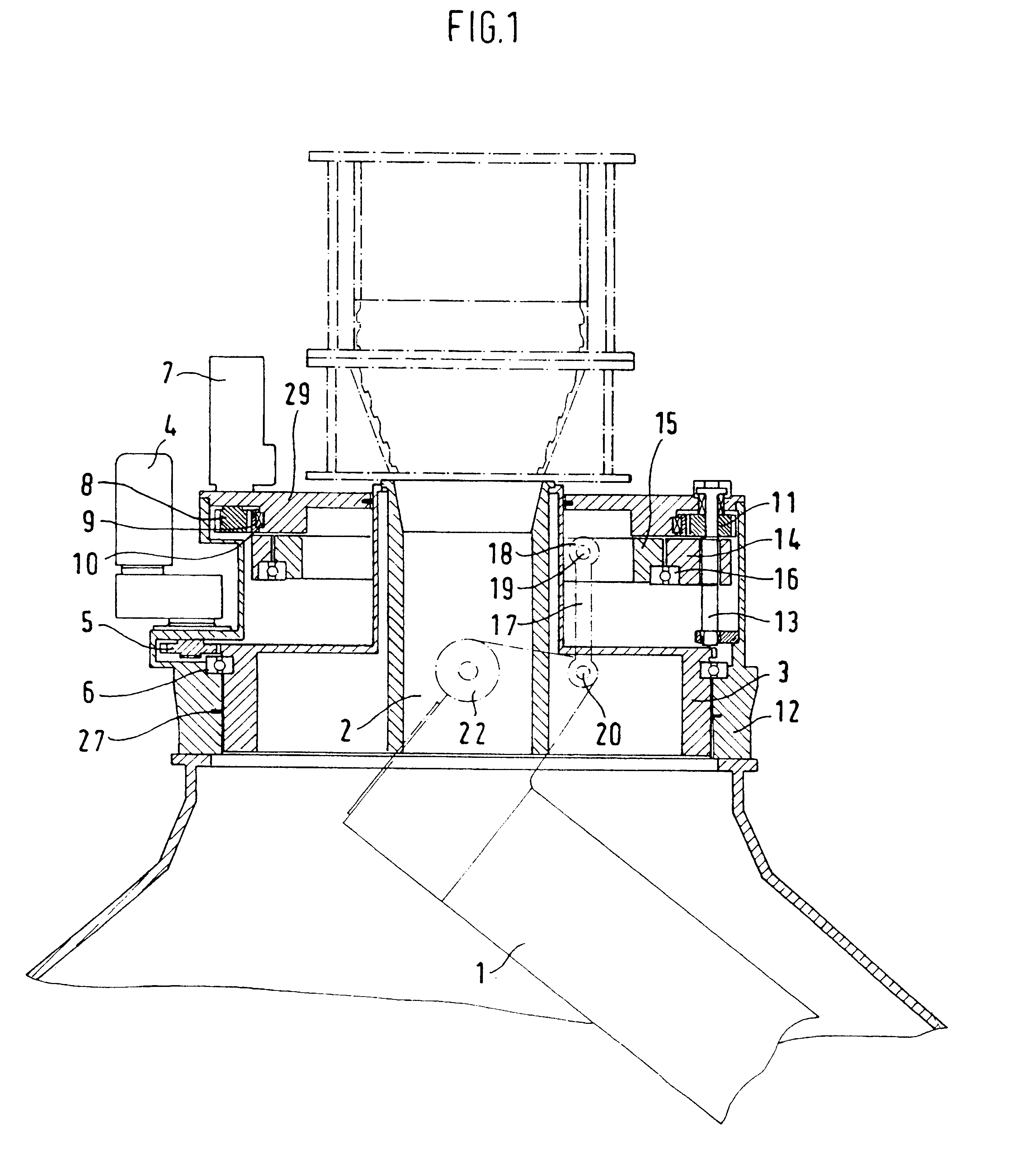
FIG. 1 shows a bell and hopper with rotatable and tiltable chute 1 for loading a blast furnace. The burden is supplied from a feed storage into a charging bin(schematically illustrated) positioned underneath. The burden, coming from the charging bin, moves via the feed tube 2 onto a tiltable and rotatable chute 1 arranged within the chute carrier and from here to the upper part of the blast furnace.

The chute carrier 3 with chute is rotated by a rotary drive, comprised of a motor 4, a pinion 5, as well as crown gear 6.

For generating the tilting movement a further motor 7 is provided which drives a crown gear 9 via a pinion 8. The drive elements are supported by means of the bearing 10. The crown gear 9 drives the respective spindle gear wheel 11 of three spindles 13 distributed about the periphery of the bell and hopper housing 12. As a result of the rotational movement, the spindle nut is lifted and lowered and entrains thus the lifting frame 14 arranged adjacently thereto. The lift...


PUM

PropertyMeasurementUnit
Pressureaaaaaaaaaa
Areaaaaaaaaaaa

Abstract

In order to configure a bell and hopper for shaft furnaces, in particular, blast furnaces, comprising a charging bin with a feed tube, a rotating chute carrier with rotary drive, a swiveling chute in the interior of the furnace with drive means arranged external to a housing, in a less failure-prone and a wear resistant way, the drive means for the swivel movement of the chute are to comprise: at least one motor (7) which drives by a respective pinion (8) a crown gear (9), wherein the crown gear (9) engages the spindle gear wheels (11) of at least two spindles (13) distributed about the periphery of the bell and hopper external to the rotating chute carrier (3) for generating a lifting and lowering movement of the spindles, as well as means (14, 15, 17, 21) for transmitting this vertical movement of the spindles onto the tilting shafts (22), which penetrate the inner wall (24) of the chute carrier (3) and from which the chute can be suspended, for generating a swivel and tilting movement of the chute.

Description

1. Field of the InventionThe invention relates to a bell and hopper for shaft furnaces, in particular, blast furnaces, comprising a charging bin with a feed tube, a rotating chute carrier with a rotary drive, and a swiveling chute in the furnace interior with drive means arranged externally.2. Discussion of Related ArtA bell and hopper of the aforementioned kind is described in German patent application 197 09 329.9. It is a bell and hopper without cone wherein the drives for the rotating and tilting movement of the chute carrier and of the chute operate independently from one another and are not in connection with the furnace interior. The chute carrier supported in a ball bearing slewing ring has a rotary drive which is comprised of an electric motor, pinion, and crown gear. The drive means for the tilting movement is disclosed in the form of a hydraulic pressure cylinder entrained in rotation by the chute carrier.This entrainment of the tilting drive on the rotating chute carrier...

Claims


Application Information

Patent Timeline
IPC IPC(8): C21B7/20C21B7/18F27B1/20
CPCC21B7/20
Inventor HEINRICH, PETEROTREMBA, WERNERHILLE, HARTMUTRICKE, MARKO
Owner PAUL WURTH SA
Why Eureka
Try Eureka