
Method for detecting forward link power control bits in a communication system

a communication system and power control technology, applied in power management, transmission monitoring, wireless communication, etc., can solve the problems of channel transmission, negative system operation, and inability of each mobile station to broadcast its own pilot sequen

Inactive Publication Date: 2003-04-01
RPX CORP +1
View PDF19 Cites 20 Cited by
  • Summary
  • Abstract
  • Description
  • Claims
  • Application Information

AI Technical Summary

Benefits of technology

According to one aspect of the invention, the present invention performs the method described above to include the different multipath components by using a rake receiver and summing the individual results of each finger to derive a better overall estimate of the transmitted power control bit.

Problems solved by technology

The reason that a pilot channel is not used on the reverse link is that it has been heretofore impractical for each mobile station to broadcast its own pilot sequence.
Decoding each power control group presents a challenge, however, in that channel imperfections and multipath effects can result in a receiver mistakenly detecting the received power control bit which may negatively impact system operation by causing forward link channels to transmit at inappropriate power levels.

Method used


Image

  • Method for detecting forward link power control bits in a communication system
  • Method for detecting forward link power control bits in a communication system
  • Method for detecting forward link power control bits in a communication system

Examples


Embodiment Construction

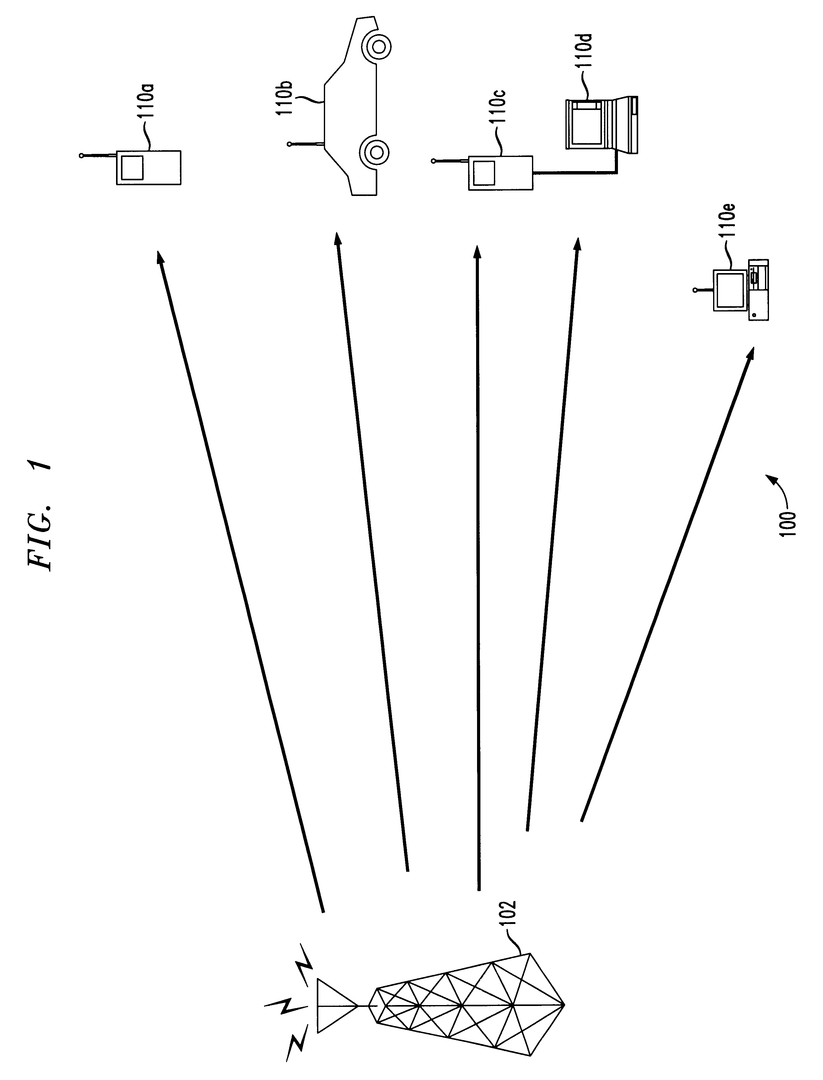
FIG. 1 is a schematic diagram illustrating a wireless communication system, designated generally by reference numeral 100 and implemented according to the present invention in which forward link power control bits are detected at the base station 102. In the wireless communication system 100, the base station 102 operates according to the code division multiple access (CDMA) protocol as per ANSI 2000 standard. Thus, a plurality of subscribing units (SUs) 110a-110d operating within the service area, communicate with the base station 102 according to the CDMA protocol. However, it is also contemplated that in other embodiments, the base station 102 and the SUs may operate according to various other communication protocols. In still further embodiments, the base station 102 and the SUs 110a-110d may operate according to multiple communication protocols.

The TIA / EIA / IS-95 standard of performing power control in a CDMA communication system generally divides power control into two general ...


PUM


Abstract

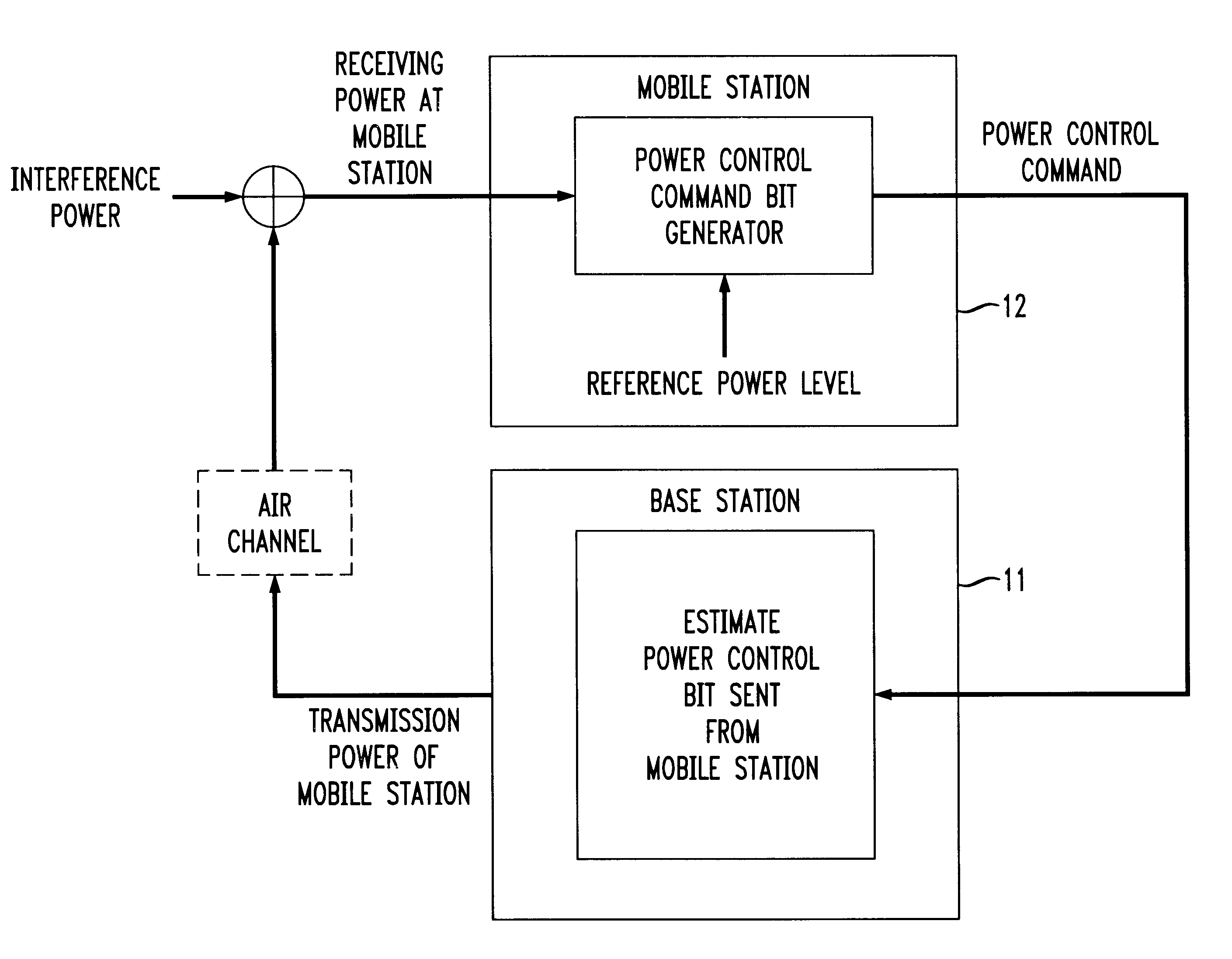
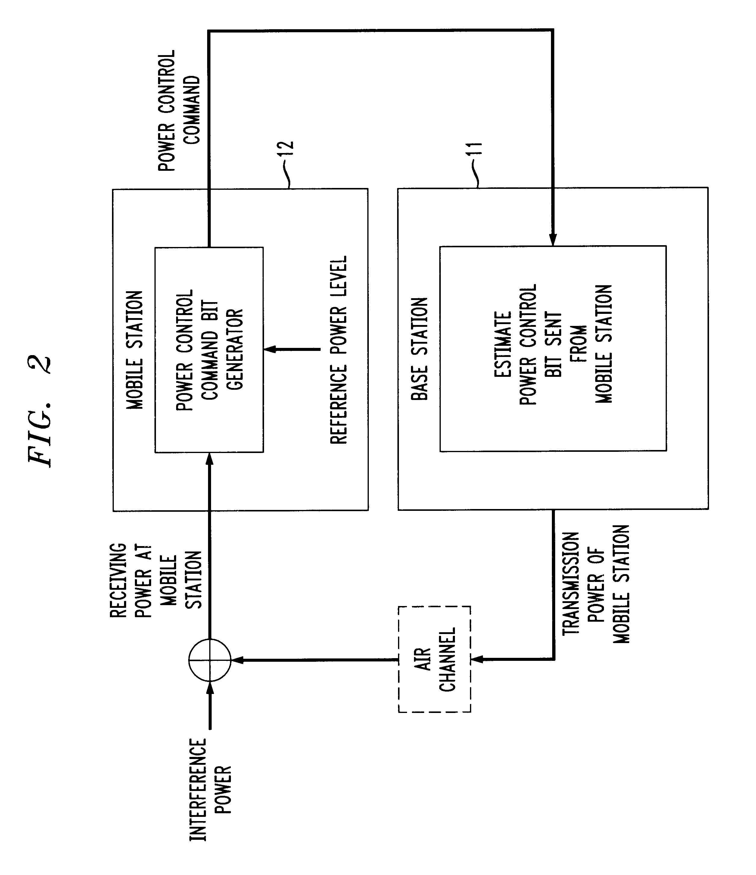
A method is disclosed for deriving an optimum decision criteria to detect forward link power control bits by a base station from a reverse link signal. In managing the forward link received power, a mobile station commands the base station to incrementally alter the forward link transmit power, by sending periodic power control bits to the base station on a reverse link signal. The transmitted power control bits may be distorted by channel imperfections and multipath effects. The method disclosed derives an optimum decision variable for performing power control bit estimation at the base station. In a preferred embodiment, the optimum decision variable is computed by considering the in-phase and quadrature components of a single power control group received on the reverse pilot channel. Both the in-phase and quadrature components of the power control are respectively made up of a pilot part containing the reverse pilot signal which is repeated over a first fixed chip duration, and a power control part containing the forward power control bit, which is repeated over a second fixed chip duration. The optimum decision variable is obtained by first summing the respective in-phase and quadrature pilot parts over their respective first chip durations, summing the respective in-phase and quadrature power control parts over their respective in-phase and quadrature components, the respective multiplication results are then summed to yield a single result.

Description

1. Field of the InventionThe invention relates generally to wireless communication systems and, more particularly, to a method for detecting forward link power control bits in a code division multiple access (CDMA) communication system.2. Description of the Related ArtThe IS-95 CDMA system is unique in that its forward and reverse links have different link structures. The forward link is made up of four types of logical channels: pilot, sync, paging, and traffic channels. The pilot channel is transmitted continuously by the base station to provide the mobile station with timing and phase reference. The reverse link is made up of two types of logical channels: access and traffic channels. The reason that a pilot channel is not used on the reverse link is that it has been heretofore impractical for each mobile station to broadcast its own pilot sequence. For this reason, a reverse pilot channel has not been suggested in IS-95.The recently announced CDMA 2000 system, as defined by the ...

Claims


Application Information

Patent Timeline
Patent Type & Authority Patents(United States)
IPC IPC(8): H04B7/005
CPCH04W52/58H04W52/08
Inventor KIM, JAEHYEONG
Owner RPX CORP
Learn More