
Characterization of microelectromechanical structures

a microelectromechanical and structure technology, applied in the direction of mechanical measuring arrangements, instruments, and mechanical means, can solve the problems of order errors in the inferred value of material properties, adversely affecting the methods used to extract material properties of mems devices, and significant geometric dimensions in such test structures

Inactive Publication Date: 2003-04-01
COVENTOR
View PDF5 Cites 20 Cited by
  • Summary
  • Abstract
  • Description
  • Claims
  • Application Information

AI Technical Summary

Problems solved by technology

Unknown and undesired variations in device geometry can also adversely affect the methods used to extract material properties for MEMS devices from MEMS test structures.
However, the measured values of the intermediate parameters depend on device geometry and are sensitive to variations in fabricated geometric dimensions.
The uncertainty introduced by variations in the fabricated geometric dimensions in such test structures is significant and introduces at least first-order errors in the inferred values of the material properties.
However, conventional ex-situ measurement techniques have various limitations and drawbacks.
Ellipsometers are specific to the substrates and layers used in device fabrication and are therefore of limited use.
However, when depth measurements smaller than .lambda. / 8 are required, errors can be introduced if the measurement techniques employed do not adjust for imperfect reflection off a device's surface or for thin-film effects resulting from internal reflection within a region of varying thickness or a gap region underneath the device.
Current methods of ex-situ and in-situ characterization have a variety of limitations and drawbacks.
As is well known, for example, coupling of a strong electrostatic drive to the mechanics can introduce electromechanical "spring softening," and in extreme cases causes pull-in, and in comb-drives can cause levitation for an in-plane drive.
In addition the lateral resonant mode is first-order insensitive to fabricated thickness variations, especially for small sidewall angles.

Method used


Image

  • Characterization of microelectromechanical structures
  • Characterization of microelectromechanical structures
  • Characterization of microelectromechanical structures

Examples


Embodiment Construction

A presently preferred embodiment of the present invention is discussed below with reference to the accompanying drawings. In the following description, numerous specific details are set forth in order to provide a thorough understanding of the presently preferred embodiment of the present invention. It will be obvious, however, to those skilled in the art that the present invention is not limited to the specific details and may be practiced with various modifications, omissions and additions thereto. For economy and clarity, similar structures are referenced throughout the drawings with the same reference numbers and in some instances, detailed depictions of well-known structures are omitted in order to avoid unnecessarily obscuring the present invention.

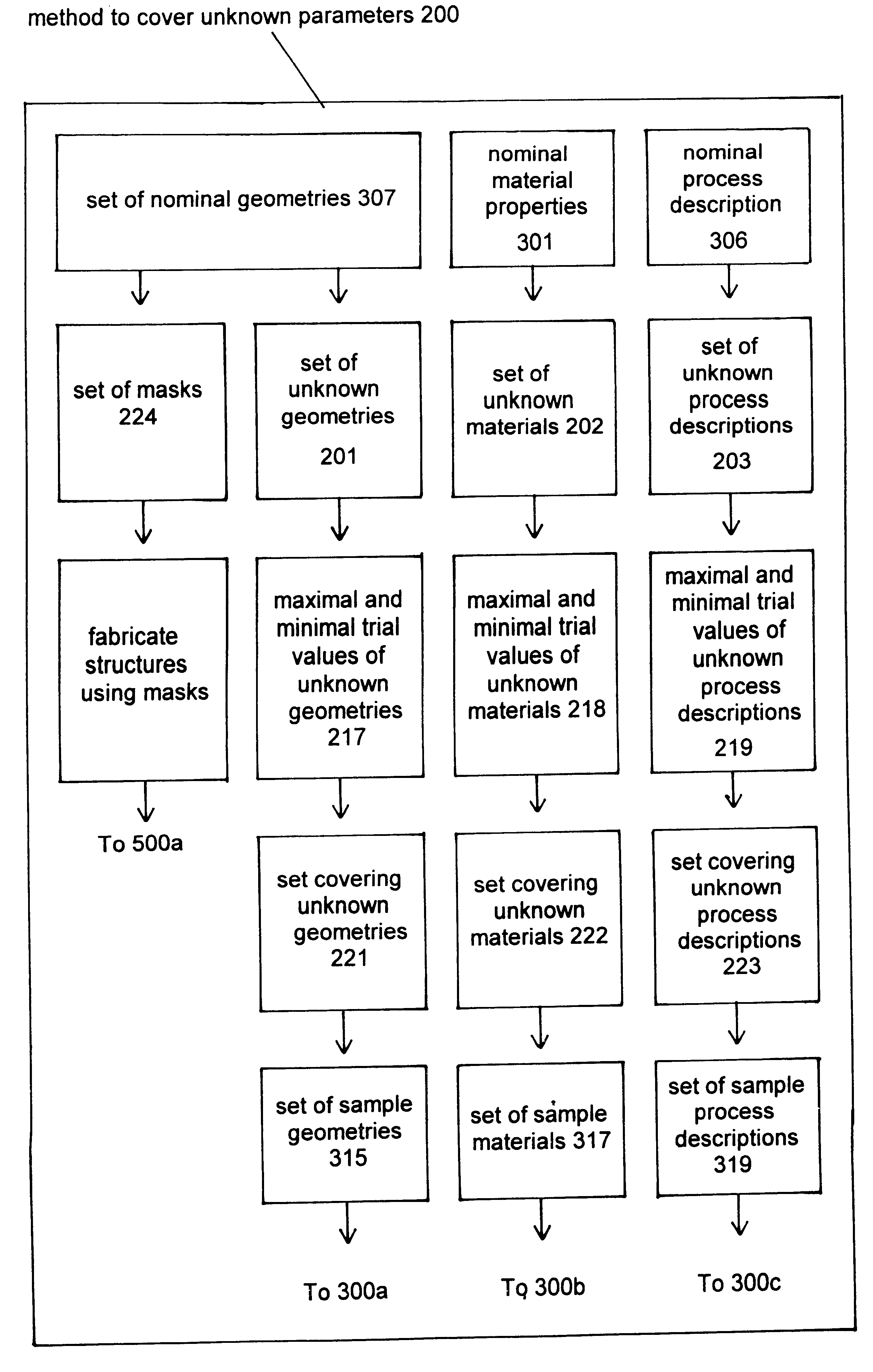
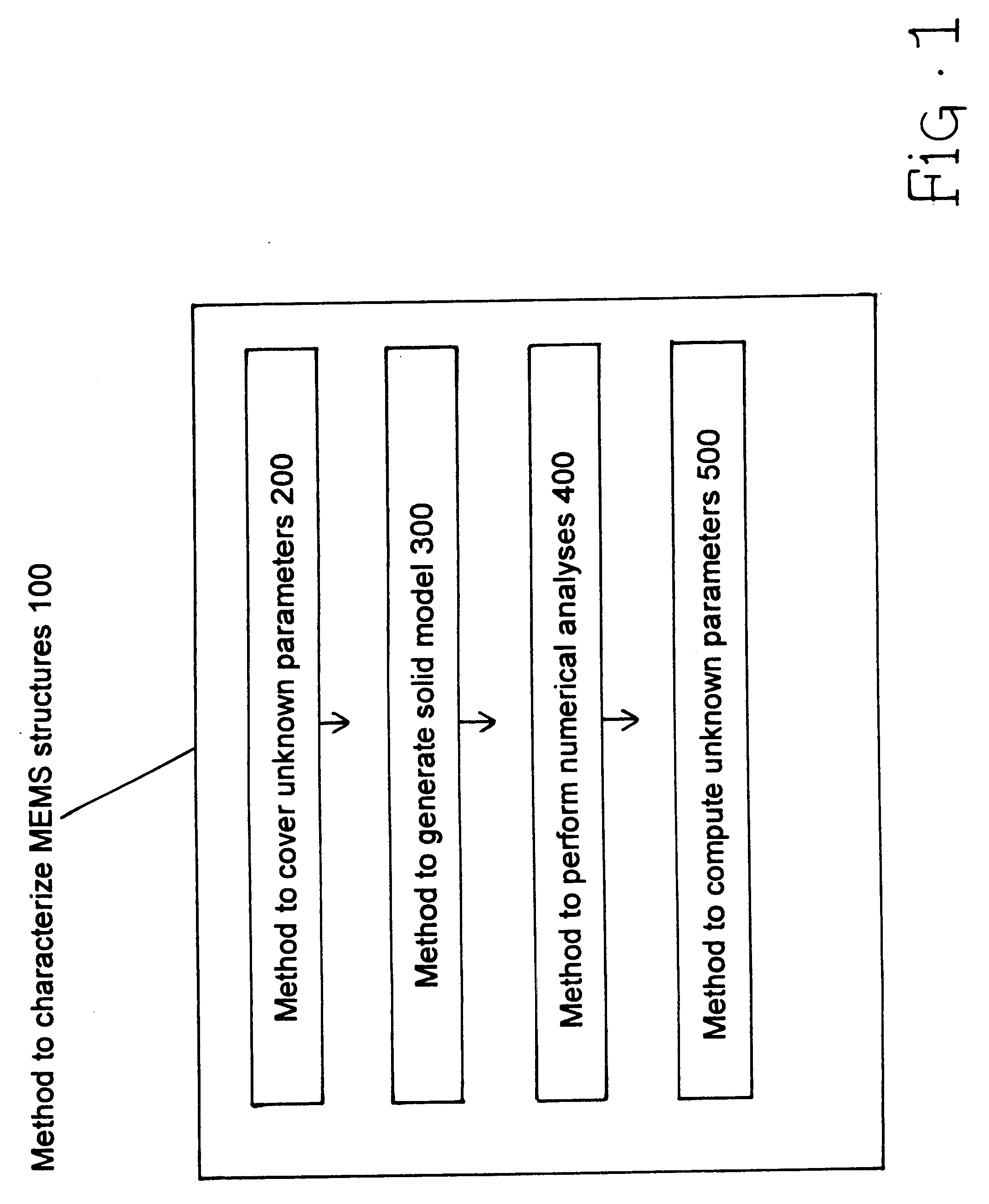
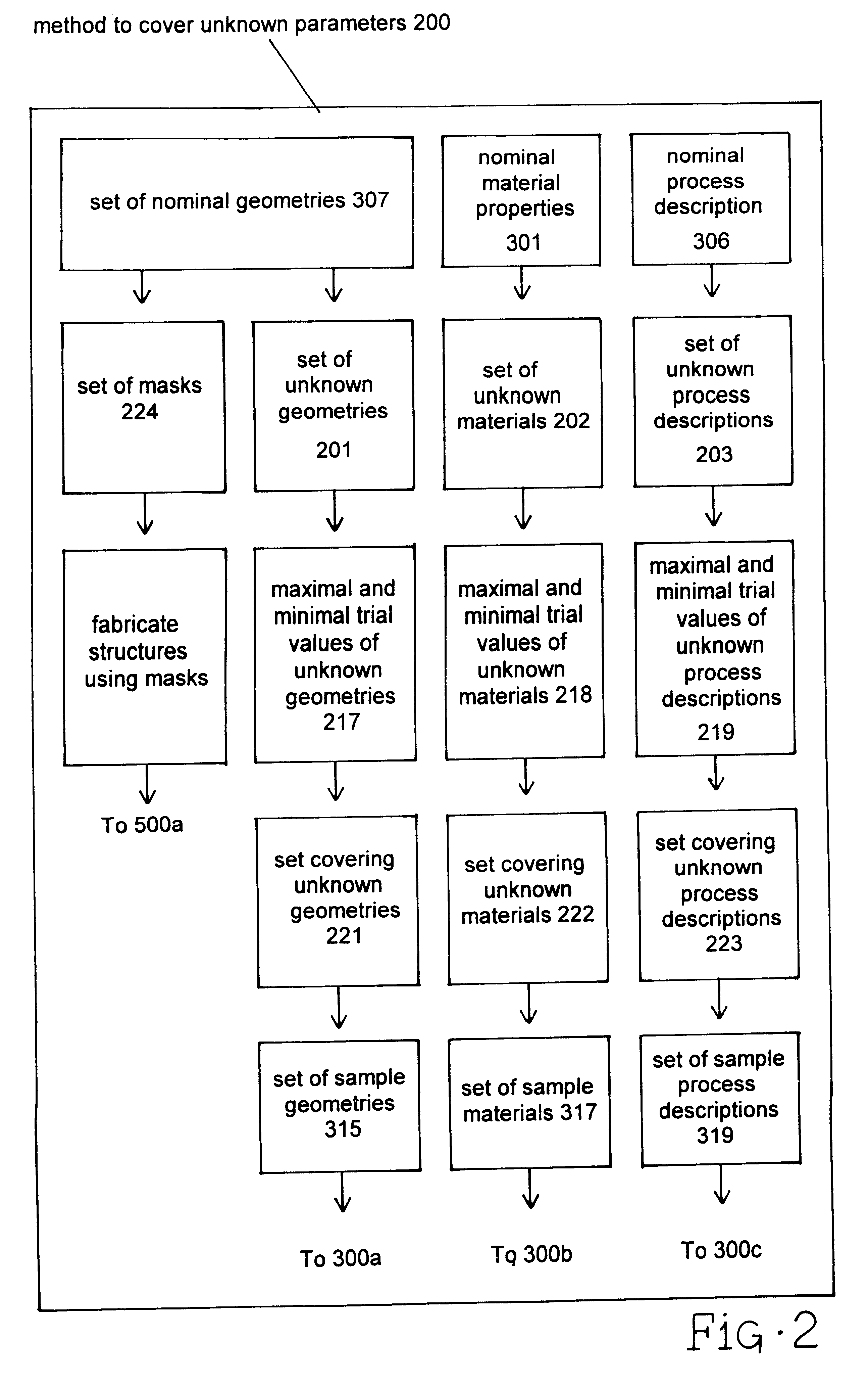
FIG. 1 generally illustrates a preferred method and components to characterize MEMS structures 100 according to the present invention. The preferred method incorporates four components. The first component comprises a preferred meth...


PUM

PropertyMeasurementUnit
Thicknessaaaaaaaaaa
Structureaaaaaaaaaa
Ratioaaaaaaaaaa

Abstract

Accurate characterization of microelectromechanical systems (MEMS) geometry is critical for device design and simulation, for material property extraction, and for post-fabrication trimming. According to the present embodiment, a method for characterizing parameters describing MEMS structures resulting from the fabrication process or process variations is presented. According to the prefered embodiment, experimentally obtained natural frequencies are compared with numerical simulations to identify unknown values of structural parameters or parameter variations. Further, the prefered embodiment teaches how electrostatically-driven laterally resonant comb-drive MEMS test structures with prescribed changes in spring width are used to characterize systematic variations in process offsets and sidewall angles. The disclosed technique is both in-situ and non-destructive.

Description

1. Field of the InventionA method for characterizing parameters describing microelectromechanical (MEMS) structures resulting from a device fabrication process or process variations is presented.2. Description of Related ArtMonitoring the geometry of fabricated MEMS devices is as fundamentally important to predicting and evaluating device performance as tracking the material properties of the devices or variations in the device fabrication processes. Accurate knowledge and predictability regarding MEMS device geometries can improve device yields and reduce the need for post-fabrication processes such as trimming to achieve targeted device performance specifications. Although material properties generally affect critical performance parameters linearly, device geometry affects device performance characteristics to much higher powers, i.e., the critical performance characteristics of fabricated MEMS devices are generally much more sensitive to variations in device geometry than to var...

Claims


Application Information

Patent Timeline
IPC IPC(8): B81C5/00H03H3/007H03H3/00B81B3/00B81C99/00
CPCH03H3/0072B81C99/006
Inventor GUPTA, RAJ K.
Owner COVENTOR
Learn More