Low cost, high performance flexible tester handler docking interface

a flexible, tester technology, applied in electronic circuit testing, printed circuit testing, printed circuits, etc., can solve the problems of high cost, large component change, and high cost of items

Inactive Publication Date: 2003-04-15
MAXIM INTEGRATED PROD INC
View PDF4 Cites 18 Cited by
  • Summary
  • Abstract
  • Description
  • Claims
  • Application Information

AI Technical Summary

Benefits of technology

The present invention discloses a method and apparatus to achieve flexible docking while avoiding the expense of hard docking and many of the performance limitations of soft docking. Through the use of high-performance, high-integrity electrical connectors instead of edge-type connectors, and dual printed circuit board "Outriggers" capable of alignment through the use of flexible supports and offset guide pins, the present invention protects the high performance connectors and all mechanical components from damage during docking. Stress-free alignment of the dual Outriggers is accomplished through the use of a robust, inexpensive keyed guide pin system and flexible joints, which also absorb mechanical stresses preventing damage to sensitive mechanical and electrical components during testing.
With the present invention, no expensive hard docking components are required to couple test head and handler, and no hard docking compatibility issues exist. Because of the flexible joint, it is possible to dock a test head and handler that could not be docked with a hard docking solution without expensive mechanical modifications and additions, such as changing the test head manipulator. Relatively inexpensive components combine for a reliable, production worthy, docking solution.

Problems solved by technology

Hard docking requires the production of precise, often bulky, mechanical components to physically lock the handler to the test head.
These items are expensive and often must be customized for each test head and handler type.
Furthermore, setup requirements may result in extensive component changes when handler type A is switched to test head type B or handler type B is changed to test head type A.
Although this prior art method results in a very secure connection of the two components and ensures high integrity signals to the device under test, the method has higher costs, skill and maintenance demands for production.
The prior art method also exhibits poor visibility for components and difficult or expensive compatibility issues.
The soft docking method benefits from low cost and simplicity, however the edge-type connectors often do not provide a high integrity AC signal path to the device under test, especially at frequencies above 10 MHz.
In addition, since there is no mechanical connection between the test head and handler, any stresses in the soft docking process can result in damage or wear to the edge connectors and excessive stress on the mechanical assemblies which hold the connectors in place.
This method is especially vulnerable to stress damage since there is nothing to take up the mechanical stress if the test head or handler is accidentally moved while the two components are docked.
The one-piece housing plate supported by the vertical posts as disclosed in the prior art is still much too rigid and fails to produce the flexible alignment and stress prevention required for docking and testing many devices.
Furthermore, the flex posts used to support the one-piece plate in the prior art lack any means to prevent overtravel between housing plate and loadboard.
Connectors may be subject to damage unless alternate travel restrictions are used to limit the clamping force used to bring the components together.

Method used


Image

  • Low cost, high performance flexible tester handler docking interface
  • Low cost, high performance flexible tester handler docking interface
  • Low cost, high performance flexible tester handler docking interface

Examples


Embodiment Construction

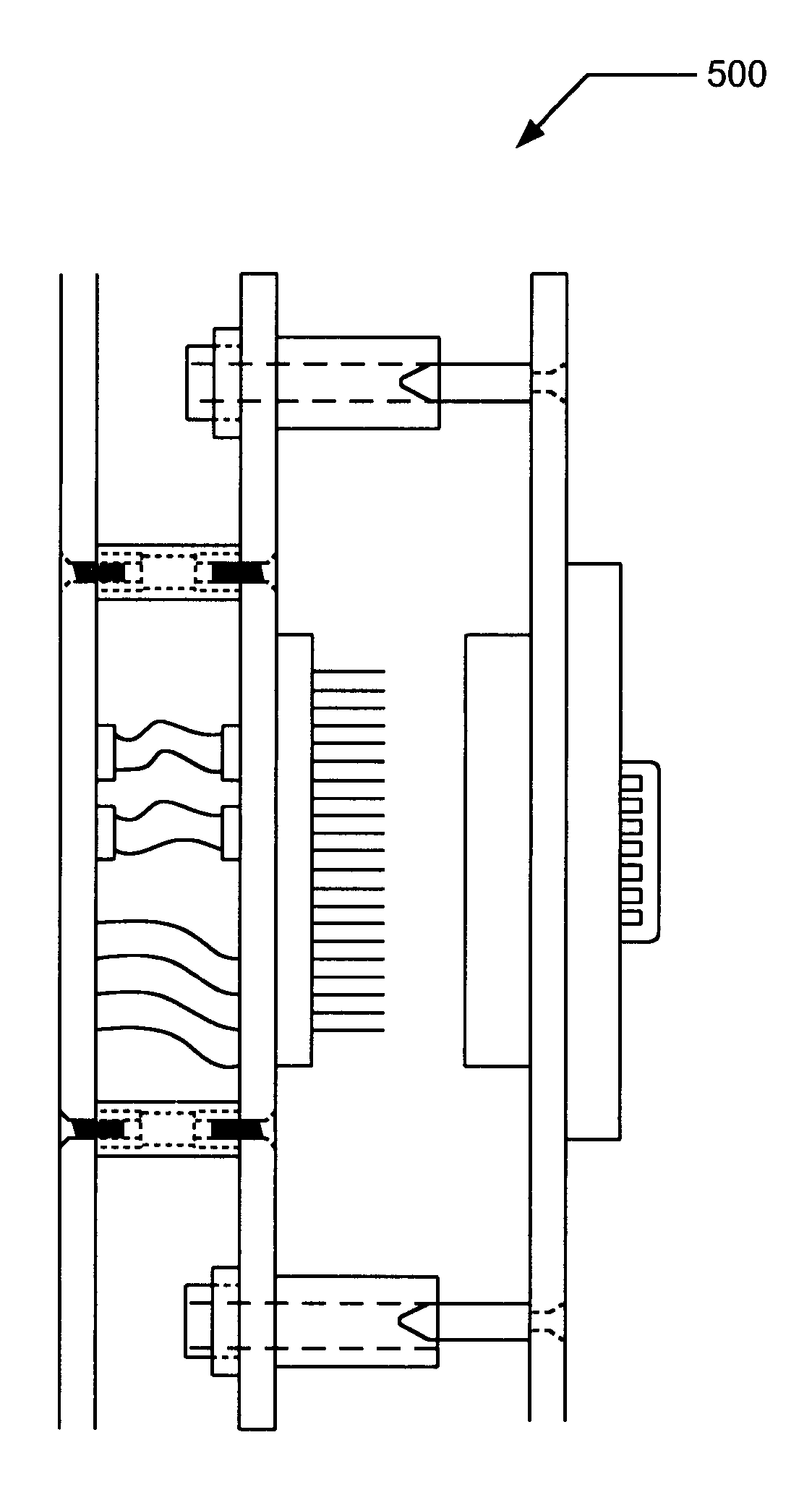
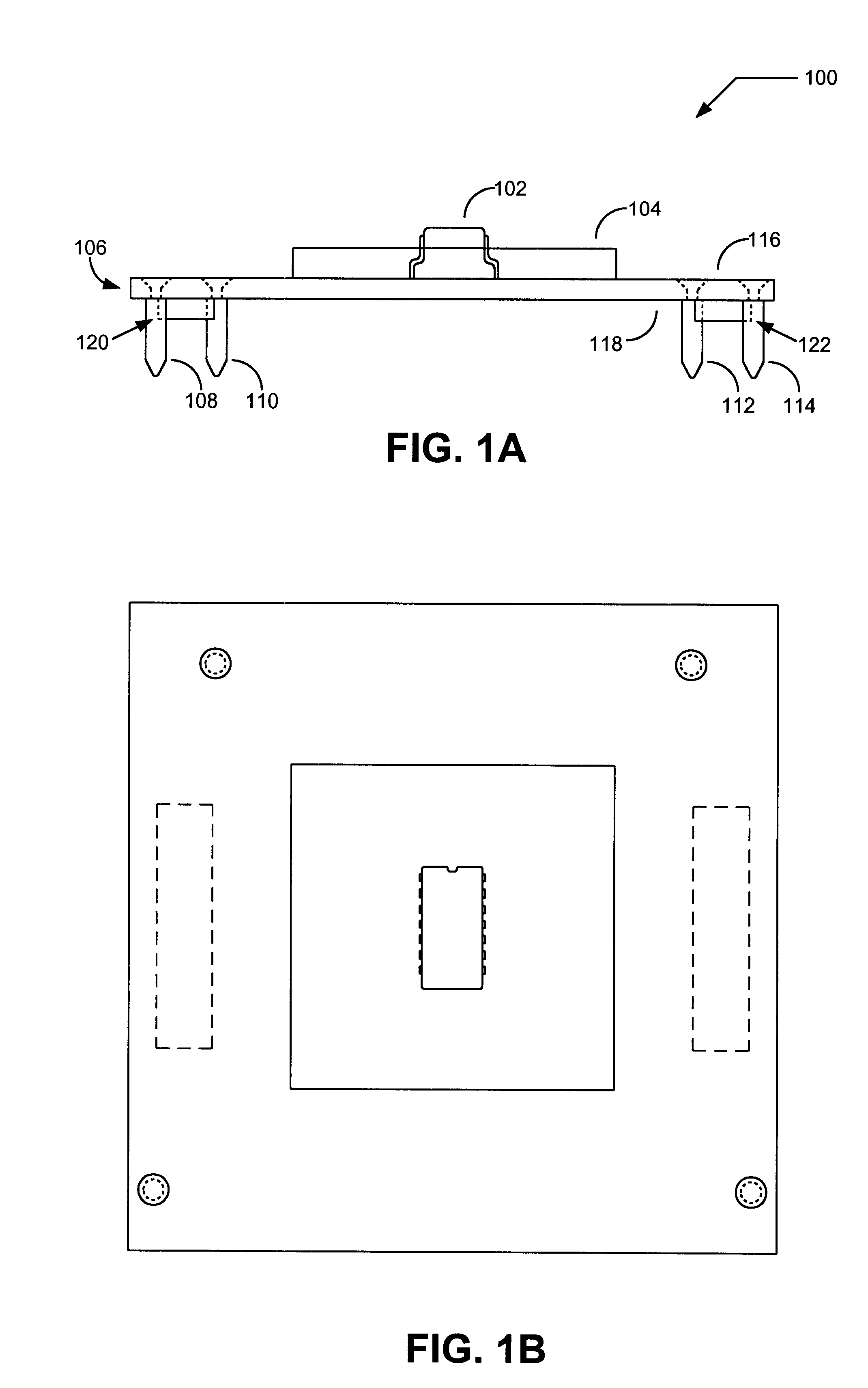
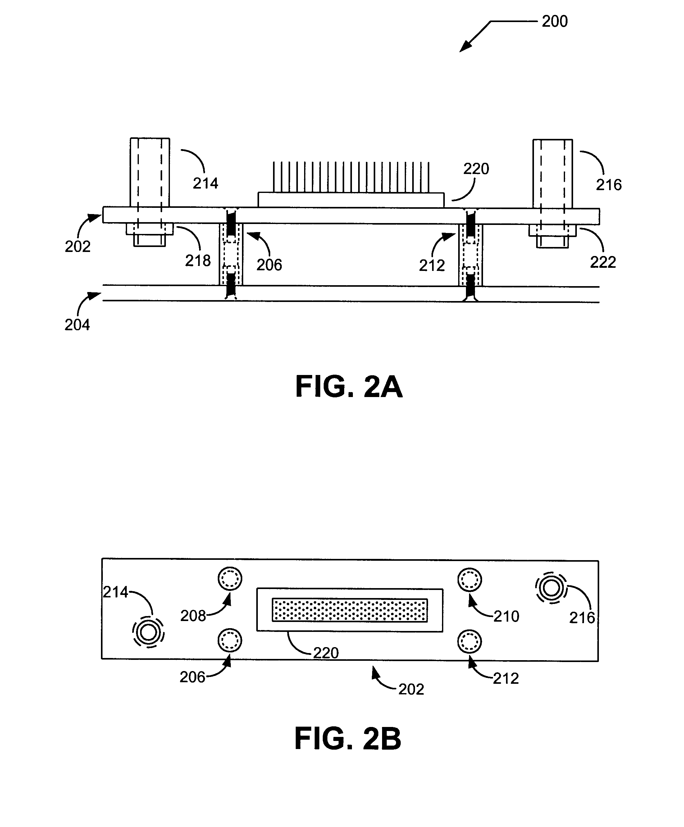
The present invention provides an improved method and apparatus to dock a handler and test head through the use of dual "Outrigger" printed circuit boards (PCBs) capable of flexible movement, allowing alignment between high performance electrical connectors on the handler and the Outriggers. The apparatus of the present invention includes the handler interface PCB, the left and right independent Outrigger PCBs, and a test head PCB. During the final operation, the handler interface PCB is mechanically attached to the handler, and the test head PCB is mechanically attached to the test head. In both cases, the integrity of the electrical signal is maintained. The handler PCB contains a high performance contactor which holds the device under test in place during testing. The device under test (DUT) may consist of a variety of package and component configurations, with different high performance contactors for each package type and different contactor PCBs for each package type and noneq...


PUM


Abstract

The present invention is related to a method and apparatus of securing and testing an IC or similar device, in which the connection of the IC is achieved through the use of a handler PCB and dual "Outrigger" PCBs connected to a test head via "flex joints". More specifically, the present invention discloses a method and apparatus to flexibly dock a handler PCB containing a device under test to a test head through the use of dual Outrigger PCBs capable of flexible movement allowing alignment between high performance electrical connectors on the handler PCB and the Outrigger PCBs, eliminating stress due to misalignments and vibration transmission during testing.

Description

BACKGROUND OF INVENTION1. Field of InventionThe present invention is related to electronic device test fixture component design and operation required during the test phase of electronic device manufacturing. More specifically, the present invention relates to the method and apparatus for the "flexible" docking of a handler, containing a high performance contactor and device under test, with a test head, using dual "Outrigger" printed circuit boards electromechanically coupled to the test head via flexible supports reducing component stress and vibration.2. Description of Related ArtPerformance of final testing on packaged parts requires the electrical connection of two large electromechanical components, the ATE (automatic test equipment) test head and the device handler. Because of the large variety of testers and the large number of different package types, test heads and handlers come in a large variety of shapes and sizes. There are currently two methods used for coupling these...

Claims


Application Information

Patent Timeline
Patent Type & Authority Patents(United States)
IPC IPC(8): G01R31/28H01R12/00
CPCG01R31/2808
Inventor ALLEN, DAVID LAWRENCEDIMLA, EDMON QUINTOROTT, DAINURI PAUL
Owner MAXIM INTEGRATED PROD INC
Why Eureka
Try Eureka