Automated minimization of optical path difference and reference mirror focus in white-light interference microscope objective

Inactive Publication Date: 2003-04-22
BRUKER NANO INC
View PDF4 Cites 36 Cited by
  • Summary
  • Abstract
  • Description
  • Claims
  • Application Information

AI Technical Summary

Benefits of technology

A final object is a procedure that can be implemented easily and economically according to the above stated criteria.
Therefore, according to these and other objectives, the present invention consists of incorporating a mechanism for producing relatively large translations of the reference optics and mirror in a white-light Linnik interference objective and carrying out PSI measurements while the OPD between the reference and test beams is varied. Utilizing the same algorithms used in the art to perform conventional phase shifting interferometry, the position of minimum OPD is determined by finding the corresponding posi

Problems solved by technology

The technique is typically limited to measurements of smooth surfaces due to a height ambiguity encountered at phase steps greater than .pi..
If a narrower bandwidth is chosen to carry out the interferometric measurements, such as with the use of a laser light, the coherence length and hence the OPD can be much greater, but stricter operational requirements render the commercial use of this type of interferometer less desirable for many applications.
In vertical-scanning, measurements are made by varying the distance F', eithe

Method used


Image

  • Automated minimization of optical path difference and reference mirror focus in white-light interference microscope objective
  • Automated minimization of optical path difference and reference mirror focus in white-light interference microscope objective
  • Automated minimization of optical path difference and reference mirror focus in white-light interference microscope objective

Examples


Embodiment Construction

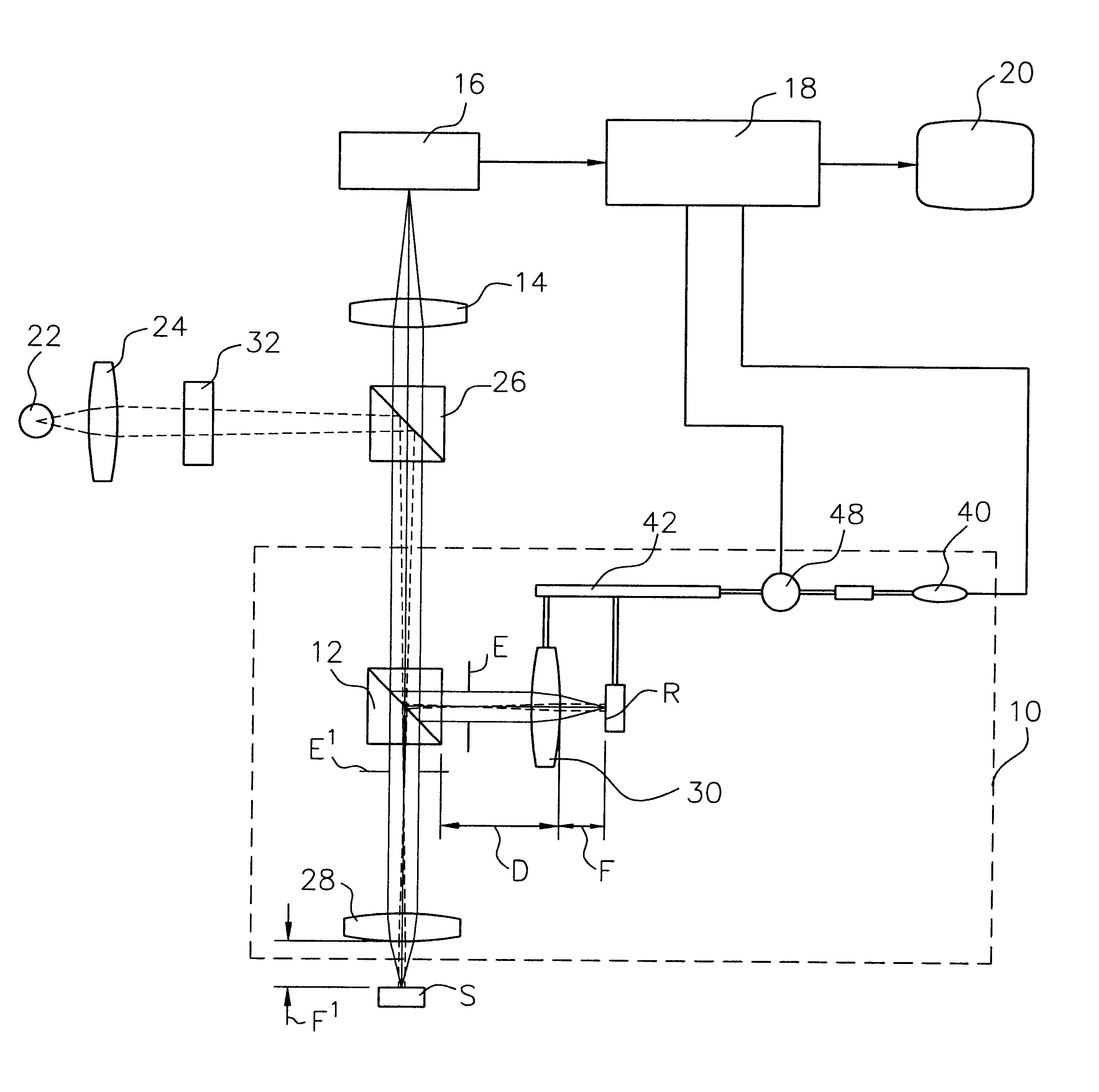
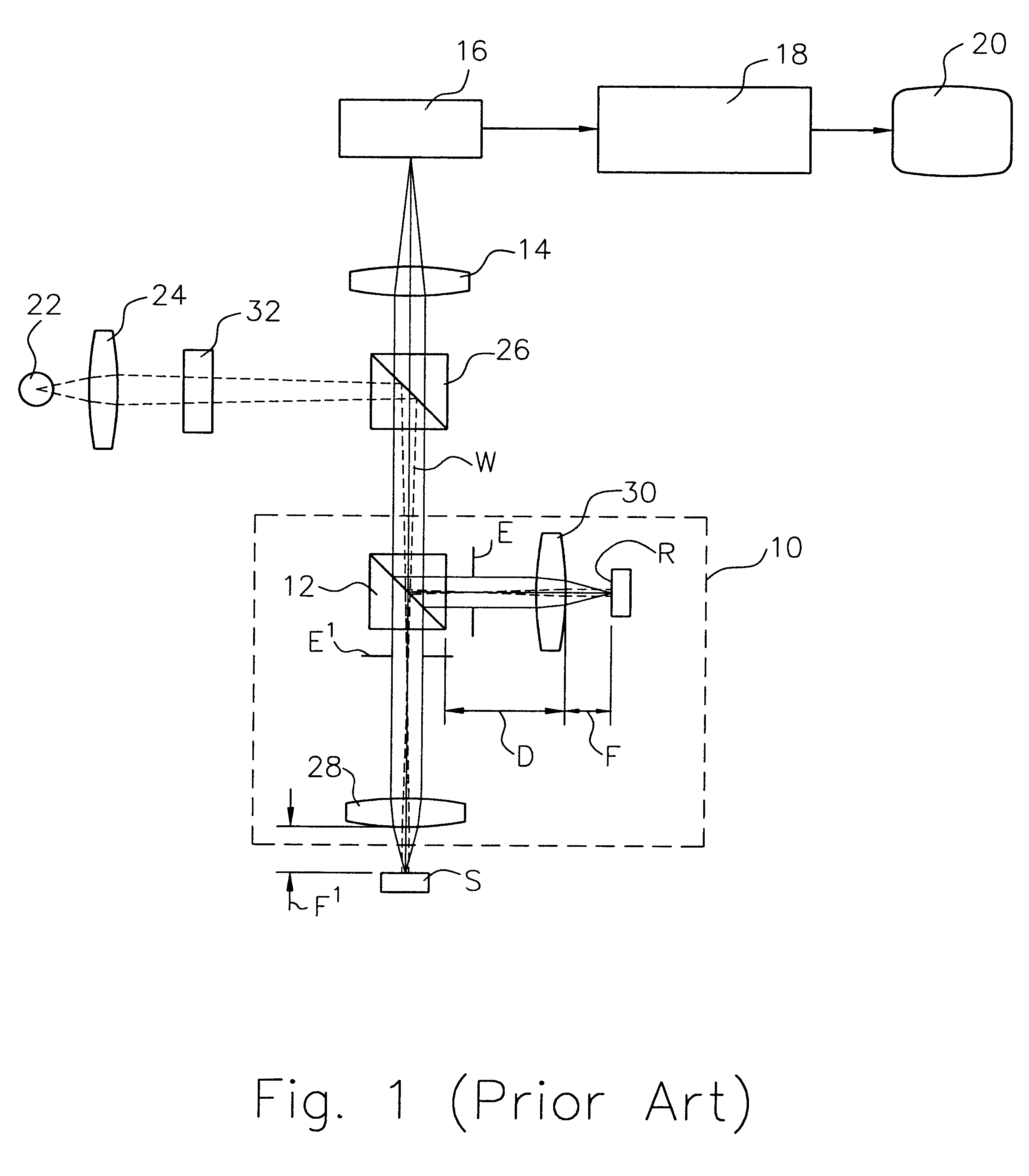
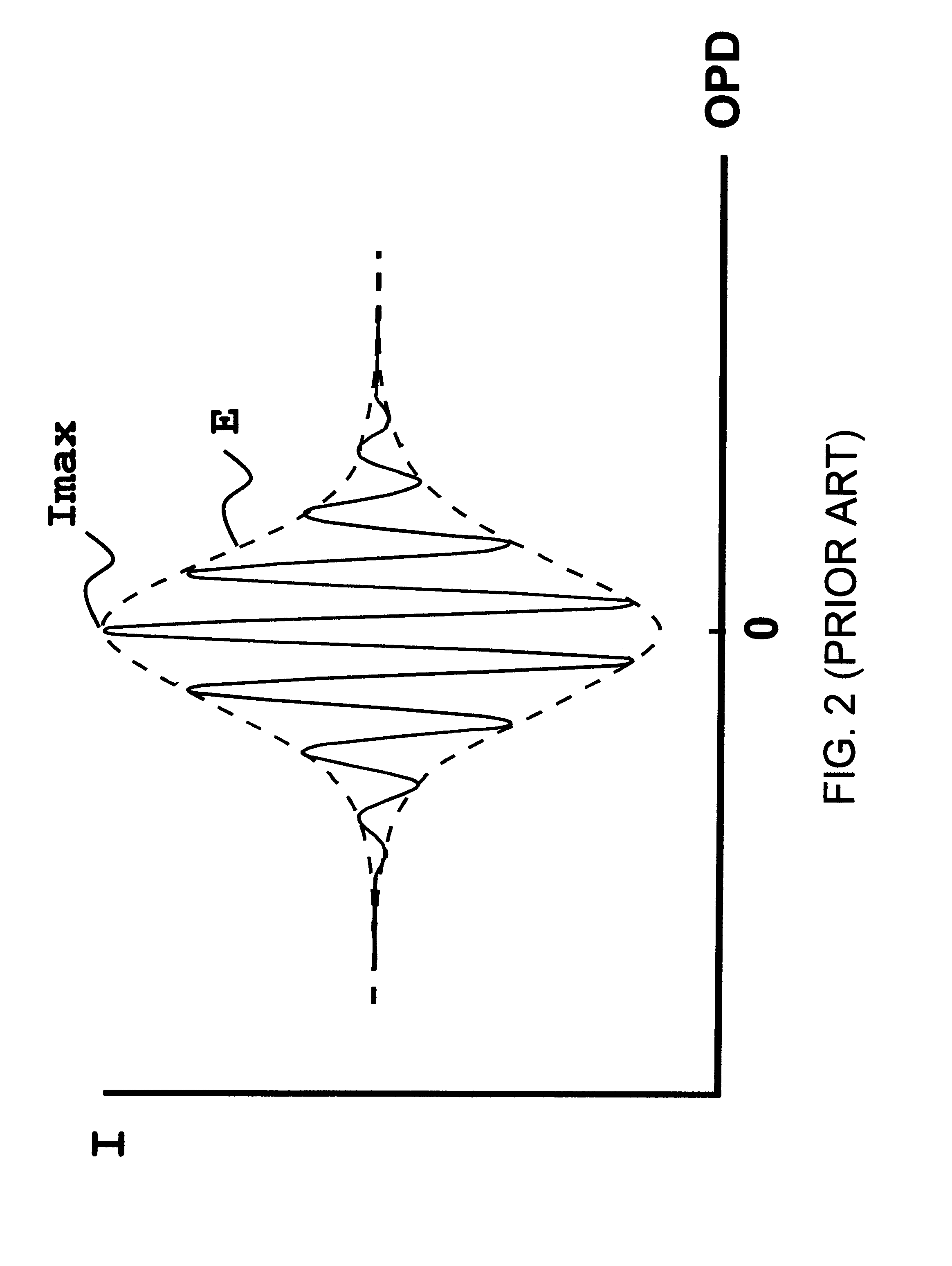
The present invention is based on the idea of maximizing fringe modulation or the spatial variation of fringe modulation in order to minimize the optical path difference between the reference path and the test path of a white-light interference objective in a white-light Linnik interferometer. The approach makes it possible to automate the process and optimize the quality of the resulting PSI or VSI profiling measurements. For the purposes of this disclosure, the term white light is intended to refer to any broad-bandwidth light such as produced by halogen lamps, arc lamps, and LEDs, which are often also filtered to reduce the bandwidth to a particular wavelength range of interest. In the examples described below, white light filtered to a 40-nm bandwidth with about 600-nm center wavelength was used. The reference symbols F, D, and F' are used to refer (as also defined above) to the distances between reference mirror and reference optics, reference optics and microscope splitter, an...


PUM


Abstract

Average fringe contrast is determined by PSI measurements at each step of relatively large translations of the reference optics and mirror of a white-light Linnik interference objective and the resulting data are used to minimize the OPD between the reference and test beam paths of the instrument. Utilizing the same algorithms used in the art to perform conventional vertical scanning interferometry, the position of minimum OPD is determined by finding the position of maximum average fringe contrast. Furthermore, by automating the system with a precise translation mechanism, operator-to-operator variations are completely eliminated and the precision of the process of OPD minimization is greatly improved. In another embodiment of the invention, the optimal focal position of the reference mirror is found at the same time by calculating the average lateral variation of fringe contrast as a function of OPD and focal position. The optimal OPD and focal position correspond to the maximum average lateral variation of fringe contrast in the resulting three-dimensional space.

Description

1. Field of the InventionThis invention is related in general to the field of interferometry and, in particular, to an automated method and apparatus for minimizing the optical path difference between the reference and the test arms of a Linnik white-light interference objective.2. Description of the Related ArtWhite-light interferometric devices typically utilize microscope objectives for simultaneously imaging a sample surface and a reference surface onto a detector in order to produce interference fringes representative of the height of the sample. As illustrated in simple schematic form in FIG. 1, a typical Linnik interference microscope includes an objective 10 focused on a test surface S and incorporating an interferometer. The interferometer comprises a beam splitter 12 and a reference mirror R such that the light beam W directed to the sample surface S is split and also directed toward the reference mirror.As is well understood by those skilled in the art, the light beams re...

Claims


Application Information

Patent Timeline
IPC IPC(8): G01B9/02
CPCG01B9/0209G01B9/02072G01B9/02087
Inventor SWINFORD, RICHARD W.AZIZ, DAVID J.GUENTHER, BRYAN W.UNRUH, PAUL R.
Owner BRUKER NANO INC
Why Eureka
Try Eureka