Co-linear tensioner and methods for assembling production and drilling risers using same

a tensioner and co-linear technology, applied in the field of production operations, can solve the problems of high maintenance costs of conventional tensioning systems, unproven cost effectiveness, and raise personnel safety concerns

Inactive Publication Date: 2003-04-29
CONTROL FLOW
View PDF21 Cites 46 Cited by
  • Summary
  • Abstract
  • Description
  • Claims
  • Application Information

AI Technical Summary

Problems solved by technology

Normal operation of these conventional type tensioning systems have required high maintenance due to the constant motion producing wear and degradation of the wire rope members.
Replacing the active working sections of the wire rope by slipping and cutting raises safety concerns for personnel and has not proven cost effective.
In addition, available space for installation and, the structure necessary to support the units including weight and loads imposed, particularly in deep water applications where the tension necessary requires additional tensioners poses difficult problems for system configurations for both new vessel designs and upgrading existing vessel designs.
Although this arrangement is an improvement over conventional wire rope systems, there are both operational and configuration problems associated with the application and vessel interface.
For example, one problem is the occurrence of rod and seal failure due to the bending induced by unequal and non-linear loading caused by vessel roll and pitch.
Additionally, these systems cannot slide off of the wellbore centerline to allow access to the well.
For example, the crew on the oil drilling vessel is not able to access equipment on the seabed floor without having to remove and breakdown the riser string.
Therefore, the present tensioner eliminates offset and the resulting unequal loading that causes rapid rod and seal failure in some previous systems.
Present methods and applications of this process require either two derricks on the drilling or production vessel or platform, or, require substantially amounts of time, and thus money, to detach and disassemble the drilling riser from the wellhead, and then assemble and attach the production riser to the wellhead using a single derrick.

Method used


Image

  • Co-linear tensioner and methods for assembling production and drilling risers using same
  • Co-linear tensioner and methods for assembling production and drilling risers using same
  • Co-linear tensioner and methods for assembling production and drilling risers using same

Examples


Embodiment Construction

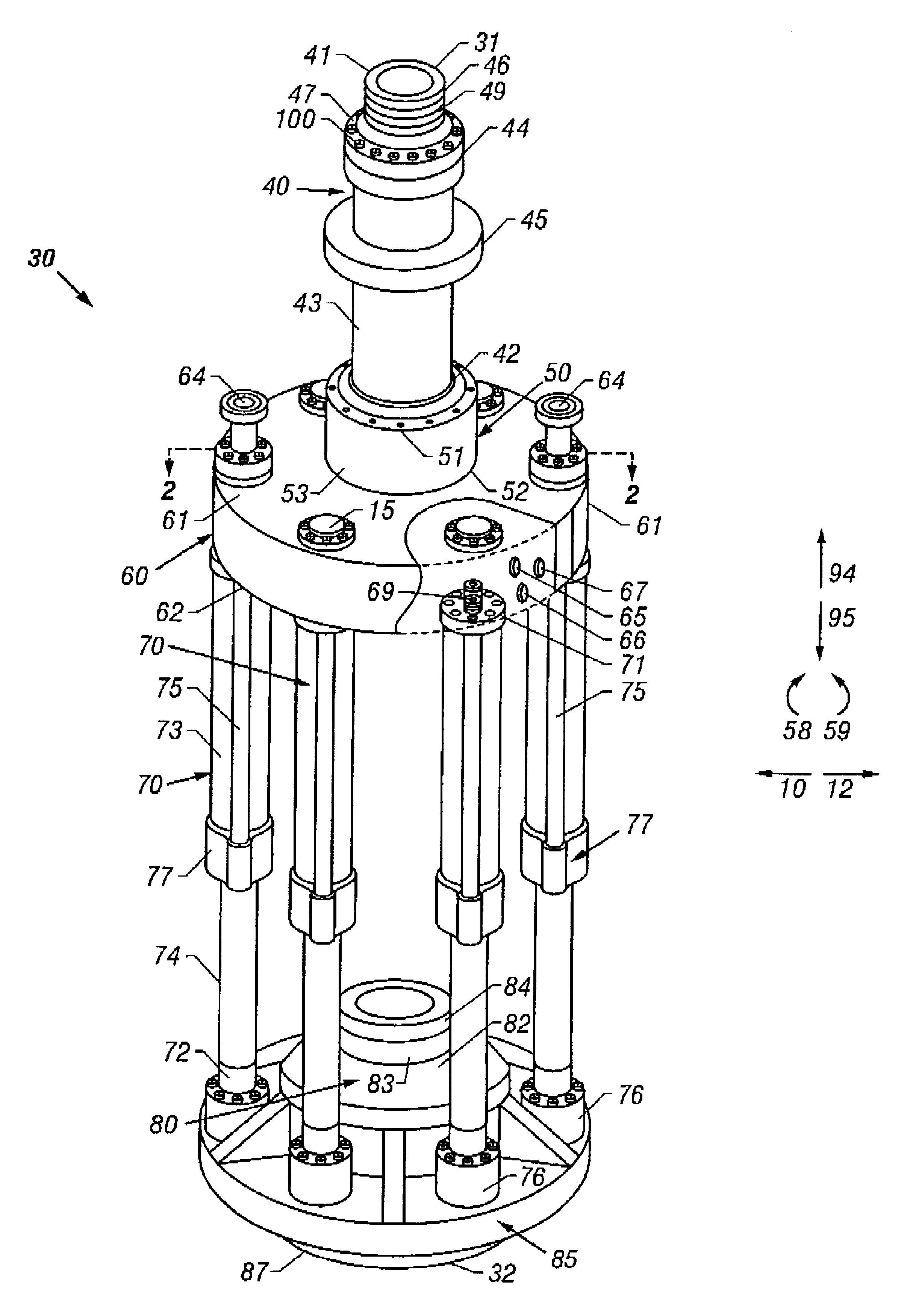
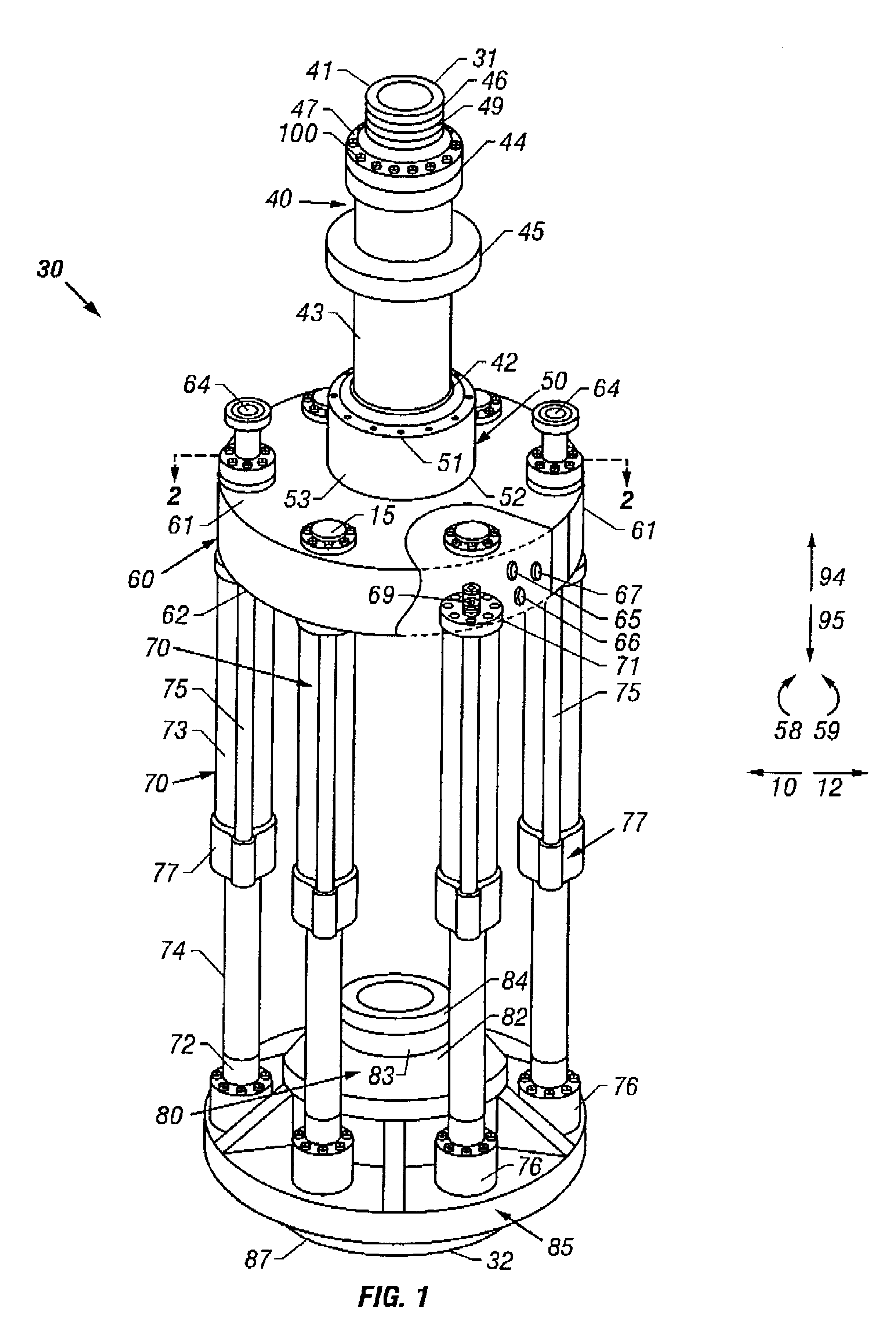
In one aspect, the invention comprises elements that when assembled form a unitary, integral, co-linear tensioner. The tensioner may be used to replace both conventional and direct acting tensioning systems. Further, variations of the tensioner may be utilized in both drilling and production riser applications.

Continuous monitoring and system management provides control of the large instantaneous loads and riser recoil / up-stroke in the event of an unplanned or emergency disconnect. Further, the system is designed to operate at a 100% level with two tension cylinders isolated which is normal practice in tensioning system operations.

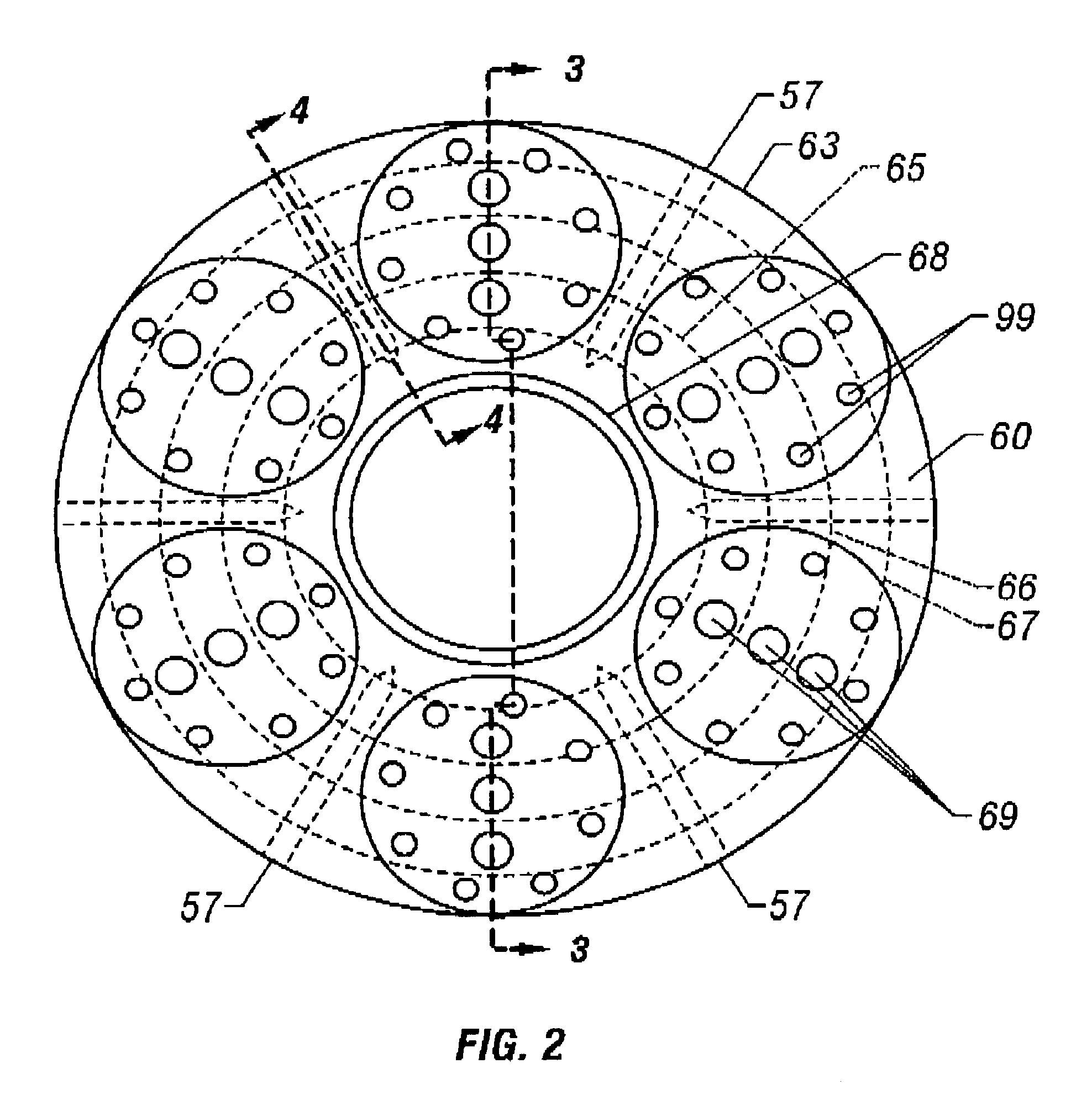
Referring now to FIG. 1, broadly, the present invention is directed to tensioner 30 having a first tensioner end 31, a second tensioner end 32, a retracted position (FIG. 7), and an extended position (FIG. 8). Preferably, tensioner 30 includes the following sub-assemblies: at least one mandrel, or spool, 40; at least one upper flexjoint, or bearing, swivel...


PUM


Abstract

A tensioner for providing a conduit, e.g., drilling and production riser strings, from a floating vessel at the surface of the ocean to the blowout preventer stack, production tree, or other assembly which is connected to the wellhead at the sea floor. The tensioner compensates for vessel motion induced by wave action and heave and maintains a variable tension to the riser string alleviating the potential for compression and thus buckling or failure of the riser string. The tensioner of the present invention preferably includes at least one mandrel having at least one hang-off donut; at least one upper flexjoint swivel assembly, at least one radially ported manifold, and at least one tensioning cylinder co-linearly combined in a single unit. Methods for assembling risers are also disclosed.

Description

1. Field of the InventionThe invention relates to offshore drilling and production operations and is specifically directed to drilling and production tensioners and risers assembled using the tensioners.2. Description of Related ArtA marine riser system is employed to provide a conduit from a floating vessel at the water surface to the blowout preventer stack or, production tree, which is connected to the wellhead at the sea floor. A tensioning system is utilized to maintain a variable tension to the riser string alleviating the potential for compression and in turn buckling or failure.Historically, conventional riser tensioner systems have consisted of both single and dual cylinder assemblies with a fixed cable sheave at one end of the cylinder and a movable cable sheave attached to the rod end of the cylinder. The assembly is then mounted in a position on the vessel to allow convenient routing of wire rope which is connected to a point at the fixed end and strung over the movable ...

Claims


Application Information

Patent Timeline
Patent Type & Authority Patents(United States)
IPC IPC(8): E21B19/00
CPCE21B19/006
Inventor MOURNIAN, TIMOTHY I.REYNOLDS, GRAEME E.
Owner CONTROL FLOW
Why Eureka
Try Eureka