Ion implanting apparatus

a technology of implanting apparatus and ion beam, which is applied in the field of implanting apparatus, can solve the problems of worsening the uniformity of the ion beam 12

Inactive Publication Date: 2003-04-29
NISSIN ION EQUIP CO LTD
View PDF3 Cites 22 Cited by
  • Summary
  • Abstract
  • Description
  • Claims
  • Application Information

AI Technical Summary

Problems solved by technology

However, since changing manners of the respective filaments 6 with time passing are ordinarily different one another, if serving the above mentioned control apparatus 20 which increases and decreases by the same amount the filament current IF flowing to the respective filaments 6, there arises a problem that the uniformity of the ion beam 12 is worsened with the time passing of the filaments 6.
This is a serious problem that the control causes hunting and does not converge.

Method used


Image

  • Ion implanting apparatus
  • Ion implanting apparatus
  • Ion implanting apparatus

Examples


Embodiment Construction

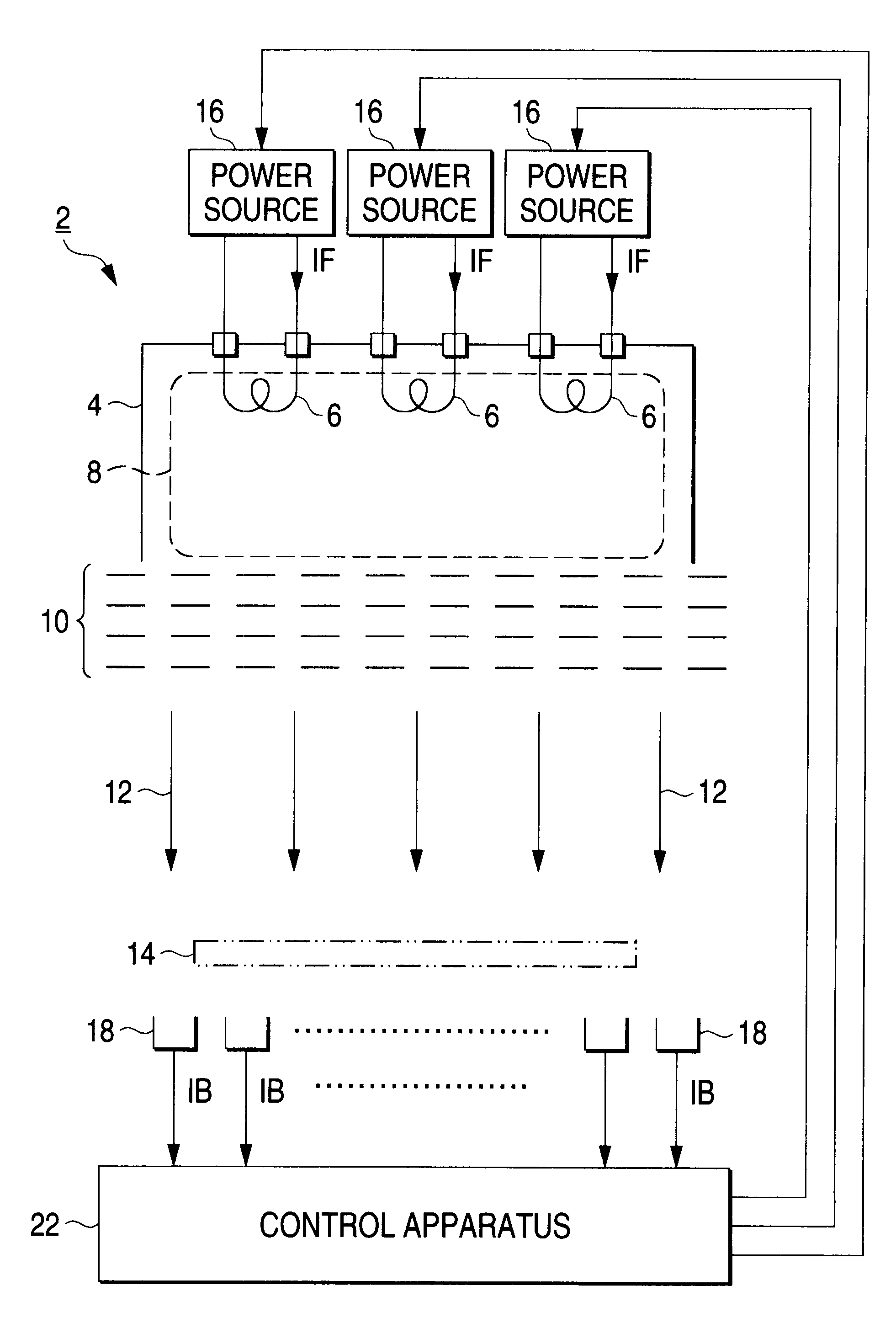
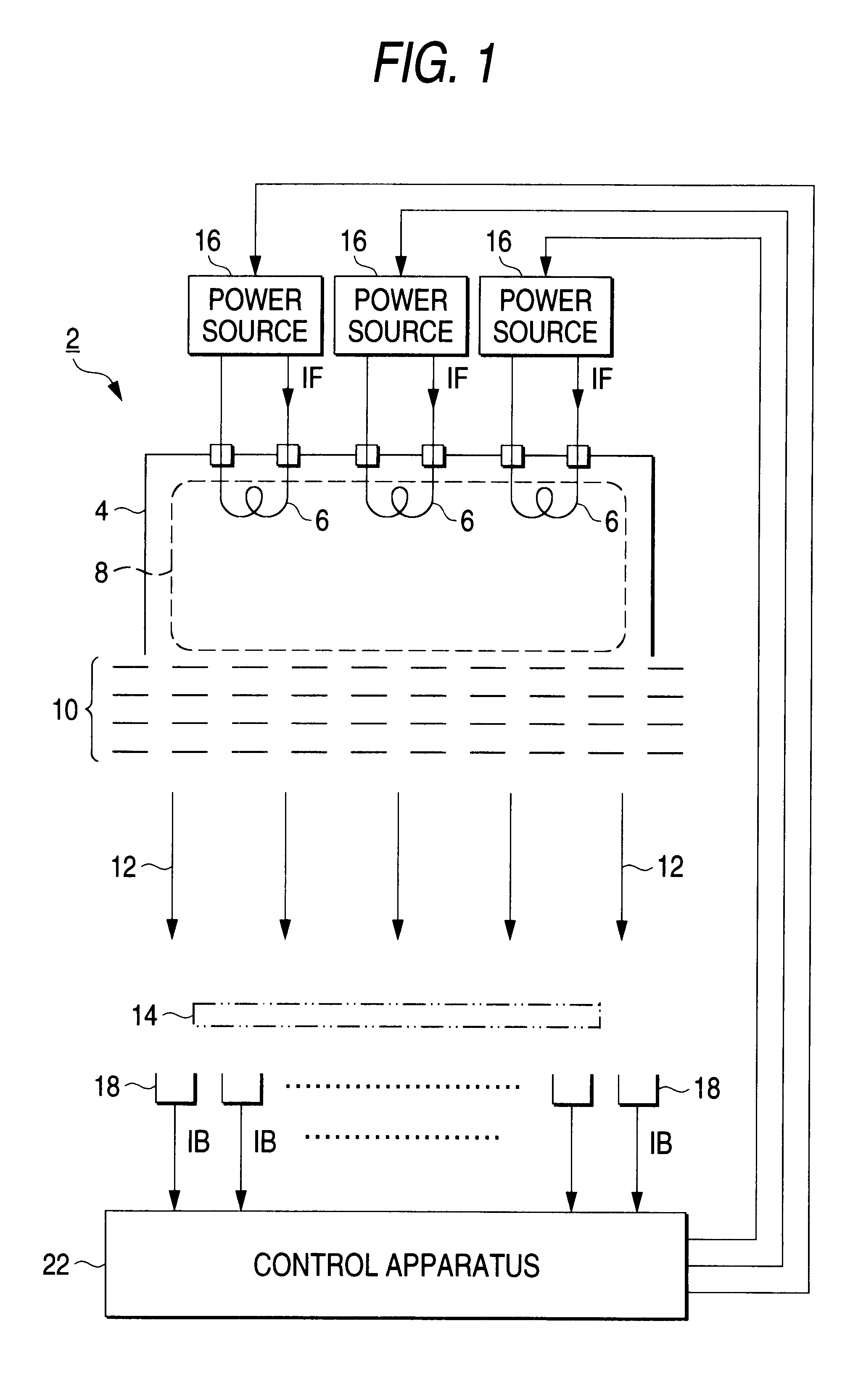
FIG. 1 is a view showing one example of the ion implanting apparatus according to the invention. The same as or corresponding parts to those of the prior art example shown in FIG. 8 will be given the same numerals, and in the following, reference will be mainly made to differences from the prior art.

The present ion implanting apparatus is equipped with a control apparatus 22 in place of the conventional control apparatus 20.

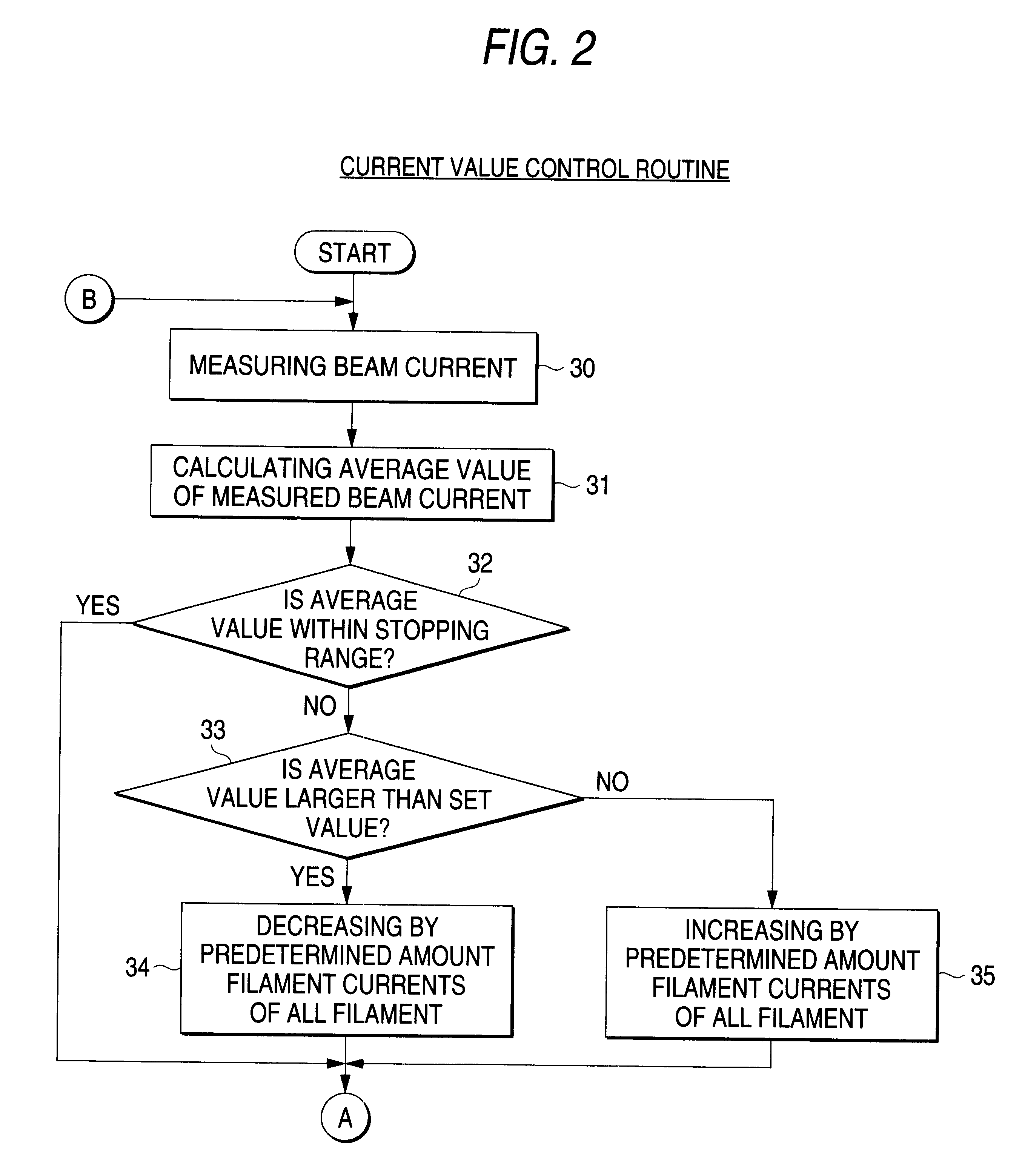
The control apparatus 22 controls the filament current IF passing to the respective filaments 6 from the filament sources 16 in accordance with the ion beam IB measured by the respective beam current measuring instruments 18, and performs the current value control routine and the uniformity control routine at least once respectively as will be stated in detail.

One example of the current value control routine is shown in FIG. 2. A schematic example of the beam profile before and after the control is shown in FIG. 7. In the following explanation, FIG. 7 will be ref...


PUM


Abstract

An ion implanting apparatus is provided with a control apparatus 22 for controlling the filament current passing to the respective filaments 6 in accordance with the beam current IB measured by a plurality of beam current measuring instruments 18. The control apparatus 22 performs, at least once respectively, {circle around (1 the current value control routine which calculates average values of all beam current measured by the beam current measuring instruments 18, and increases and decreases the respective filament current IF such that the average value comes near to the set value, and {circle around (2 the uniformity control routine which groups the beam current measuring instruments 17 into the number of the filaments, seeks for a maximum value and the minimum value from all the measured values of the beam current IB, decides groups to which the maximum value and the minimum value belong, decreases the filament current IF passing to the filaments 6 corresponding to the maximum value, and increases the filament current IF passing to the filaments 6 corresponding to the minimum value.

Description

1. Field of the InventionThe present invention relates to an ion implanting apparatus of carrying out ion implanting by irradiating to a substrate ion beam brought out from an ion source having a plurality of filaments, and in particular an improvement of means for controlling beam current of the ion beam brought out from the ion source to be at a predetermined value and an excellent uniformity as well.2. Description of the Related ArtA conventional example of this kind of ion-implanting apparatus is shown in FIG. 8. This ion implanting apparatus is also called as an ion doping apparatus (or an ion implanting apparatus of non-mass separating type) which directly irradiates to a substrate 14 an ion beam 12 of large area brought out from the ion source 2 as it is, not passing through a mass separator, so as to carry out the ion implanting to the substrate 14. When implanting the ion, if required, the substrate 14 may be mechanically scanned within an area of implanting the ion beam, f...

Claims


Application Information

Patent Timeline
Patent Type & Authority Patents(United States)
IPC IPC(8): H01J37/304H01J37/317H01J37/30
CPCH01J37/304H01J37/3171H01J2237/0822
Inventor KONISHI, MASASHIMAENO, SHUICHIANDO, YASUNORI
Owner NISSIN ION EQUIP CO LTD
Why Eureka
Try Eureka