External cavity laser using angle-tuned filter and method of making same

an angle-tuned filter and laser technology, applied in the direction of laser optical resonator construction, laser details, optical resonator shape and construction, etc., can solve the problems of mechanical vibration, large volume, and inability to adjust the precision tuning mechanism, so as to eliminate or at least mitigate the disadvantages of such known external cavity lasers

Inactive Publication Date: 2003-04-29
NEWPORT CORP
View PDF15 Cites 33 Cited by
  • Summary
  • Abstract
  • Description
  • Claims
  • Application Information

AI Technical Summary

Benefits of technology

The present invention seeks to eliminate or at least mitigate the disadvantages of such known external cavity lasers.

Problems solved by technology

A disadvantage of the bulk grating kind of external cavity laser is that it tends to be rather bulky.
Although angle-tuned filter external cavity lasers are less bulky, a disadvantage they share with bulk grating designs is that the mechanical system for tilting the filter, like the grating, must be very precise, which tends to increase manufacturing costs by an unacceptable amount.
Moreover, the precision tuning mechanism is very susceptible to changes in temperature, mechanical vibration, and so on.
Although Zorabedian's design reduces the requirement for the precise positioning of the mirror, cost savings and reduced losses are not fully realised because the number of discrete components is increased, which tends to complicate assembly and increase the cost of manufacture.
Hence, known designs are still expensive to make to achieve the necessary precision and ensure that losses are acceptable.

Method used


Image

  • External cavity laser using angle-tuned filter and method of making same
  • External cavity laser using angle-tuned filter and method of making same
  • External cavity laser using angle-tuned filter and method of making same

Examples


Embodiment Construction

In the drawings, corresponding components in the different Figures have the same reference numeral, but in some cases with a suffix.

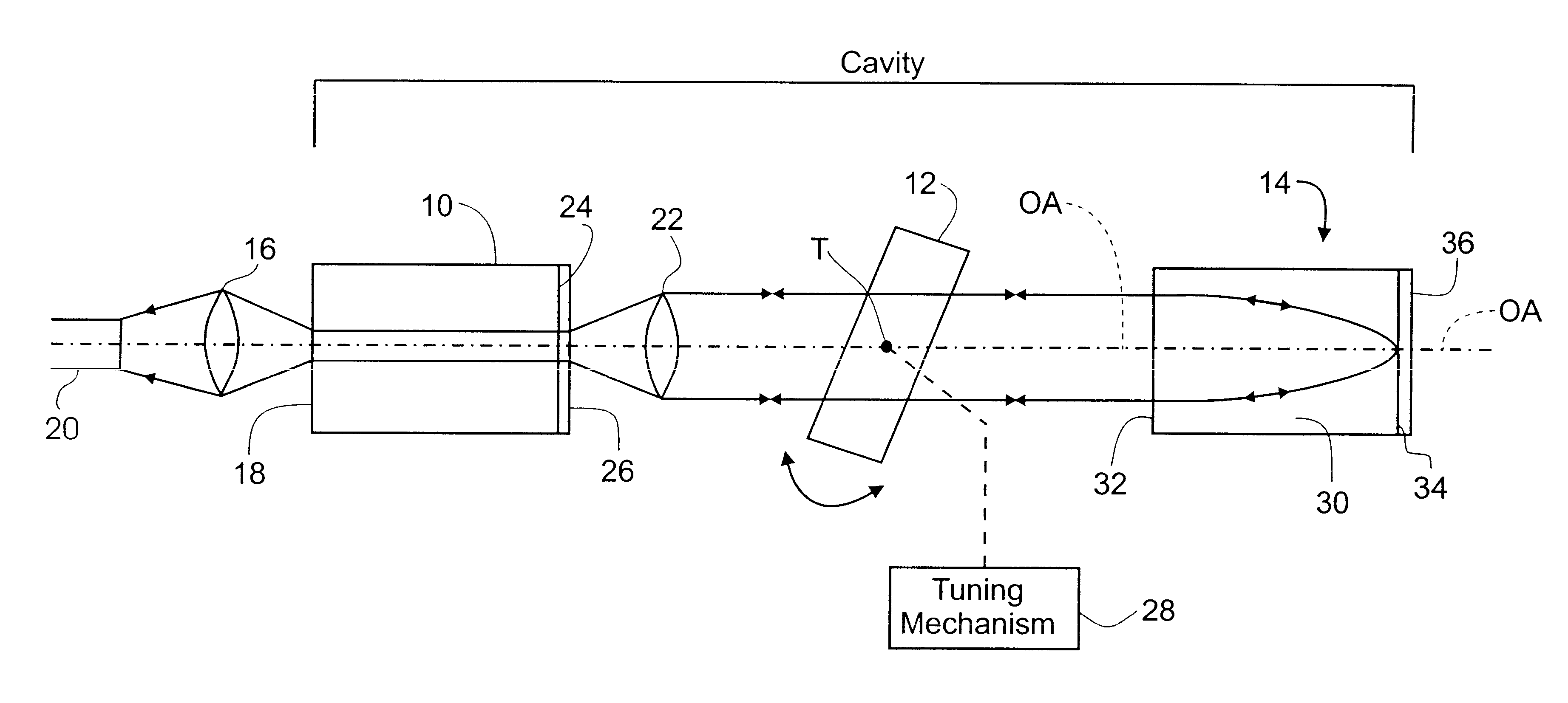
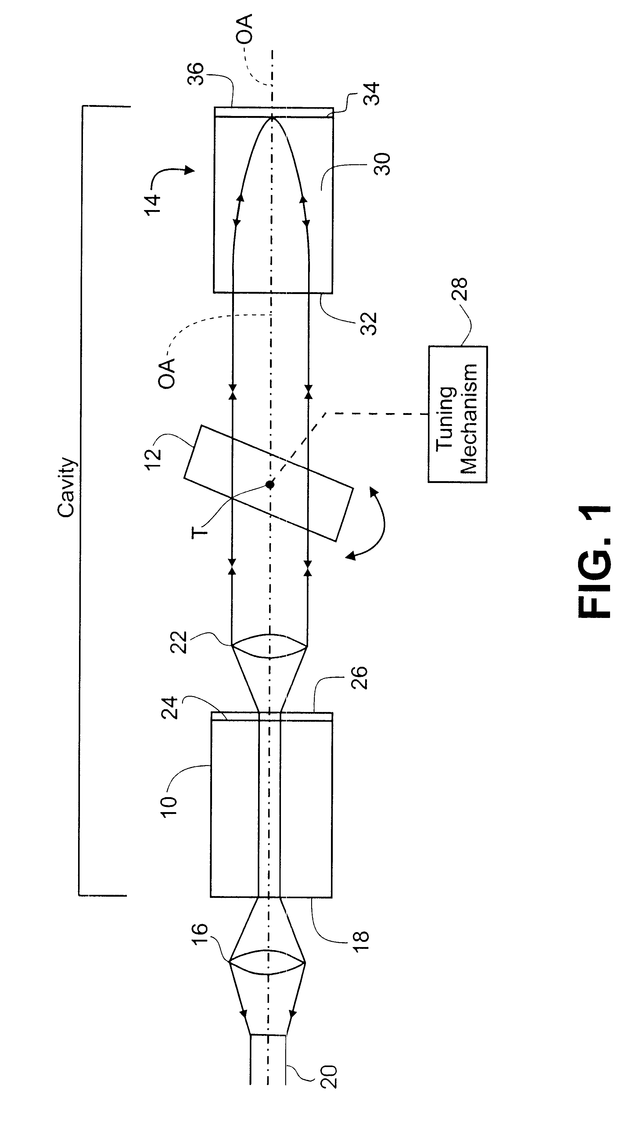
The external cavity laser illustrated in FIG. 1 comprises a semiconductor light source 10, an angle-tuned filter 12, conveniently a narrowband transmission filter with a -3 dB bandwidth from 0.1 nm to 10.0 nm, for example, and a unitary retroreflector 14. A first lens 16 focuses light for output from a rear facet 18 of the light source 10 into, for example, an optical fiber 20 and a second lens 22 at the opposite end of the light source collimates light from a front facet 24 of the light source 10 and directs it through the angle-tuned filter 12 with the beam axis substantially parallel to an optical axis OA common to both the light source 10, lens 22 and angle-tuned filter 12. An anti-reflection coating 26 is provided on the front facet 24.

The orientation of the optical axis OA is determined by the relative alignment of the light source 10 and the coll...


PUM


Abstract

An external cavity laser comprises a light source unit, preferably comprising a semiconductor light source having internal optical gain and a collimating lens, for supplying substantially collimated light to a retroreflector via an angle-tuned filter extending across an optical axis of the light source. The retroreflector is positioned so as to receive light from the light source via the angle-tuned filter and reflect the light via the angle-tuned filter back to the light source. The retroreflector may comprise a quarter pitch graded-index (GRIN) lens having a proximal end surface oriented towards the light source and a distal end surface opposite thereto, with a mirror provided on the distal end surface, preferably as a high-reflectance coating. The angle-tuned filter may be attached to the proximal end surface of the GRIN lens, preferably as a coating. The GRIN lens may be tilted in order to vary the angle of the filter relative to the optical axis and hence the wavelength. Where the external cavity laser is to be wavelength-adjustable in use, the external cavity laser may further comprise a tuning mechanism for tilting the angle-tuned filter. Alternatively, the tilt angle of the angle-tuned filter may be adjusted and then fixed during manufacture using a separate tilting mechanism which is not a part of the external cavity laser itself.

Description

This invention relates to external cavity lasers of the kind which employ a retroreflector and an intra-cavity angle-tuned filter, and is applicable to both tunable lasers and fixed-wavelength lasers. The invention is also applicable to a method of making such fixed-wavelength lasers.It is well known to add an external cavity to a semiconductor laser to increase intensity at a given wavelength. It is also known to use a fiber grating in the external cavity to select the wavelength at which the laser emits. If only one output wavelength is desired, a simple grating may suffice. If more than one wavelength is required, however, it is known to use a bulk diffraction grating and tilt it relative to the optical axis of the laser to select different operating wavelengths. It is also known for an external cavity laser that is tunable to different wavelengths to have a mirror and an angle-tuned filter forming the external cavity. A disadvantage of the bulk grating kind of external cavity la...

Claims


Application Information

Patent Timeline
Patent Type & Authority Patents(United States)
IPC IPC(8): H01S5/14H01S5/00H01S5/022
CPCH01S5/141H01S3/1062
Inventor SVILANS, MIKELIS NILS
Owner NEWPORT CORP
Why Eureka
Try Eureka