External cavity laser light source

a laser light source and laser light source technology, applied in the direction of laser optical resonator construction, laser details, optical resonator shape and construction, etc., can solve the problems of preventing lasing of fp-ld, sld is not suitable for wdm-pon, and low lasing yield, etc., to achieve good characteristics, low power consumption, and high gain

Active Publication Date: 2010-09-23
ELECTRONICS & TELECOMM RES INST
View PDF18 Cites 35 Cited by
  • Summary
  • Abstract
  • Description
  • Claims
  • Application Information

AI Technical Summary

Benefits of technology

[0007]The present invention provides a superluminescent diode (SLD) that can emit a circular light having a narrow far field pattern (FFP), while having high gain in a low current condition, low power consumption characteristics owing to its low threshold current value, and good high-frequency modulation characteristics at more than 1.25 Gb / s.
[0008]The present invention also provides a reflective semiconductor optical amplifier (R-SOA) that can emit a circular light having a narrow far field pattern (FFP), while having high gain in a low current condition, low power consumption characteristics owing to its low threshold current value, and good high-frequency modulation characteristics at more than 1.25 Gb / s.

Problems solved by technology

Although the output facet of an FP-LD has a reflectivity of less than 0.1% by anti-reflection coating, it is generally difficult to prevent lasing of the FP-LD, and the lasing yield is reduced.
In this case, although the reflectivity of the output facet can be reduced, the SLD is not suitable for a WDM-PON due to an increased threshold current and operational current.

Method used


Image

  • External cavity laser light source
  • External cavity laser light source
  • External cavity laser light source

Examples


Embodiment Construction

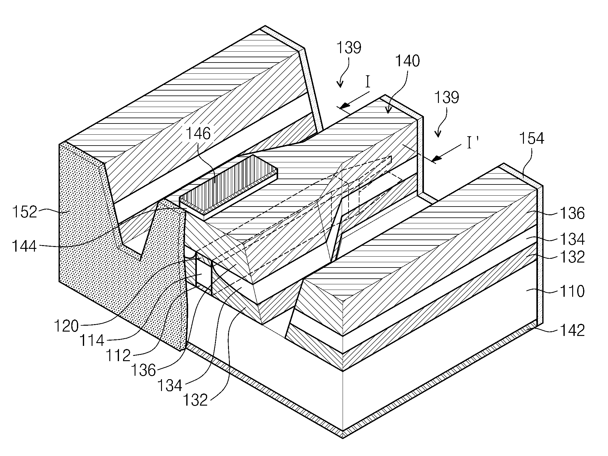
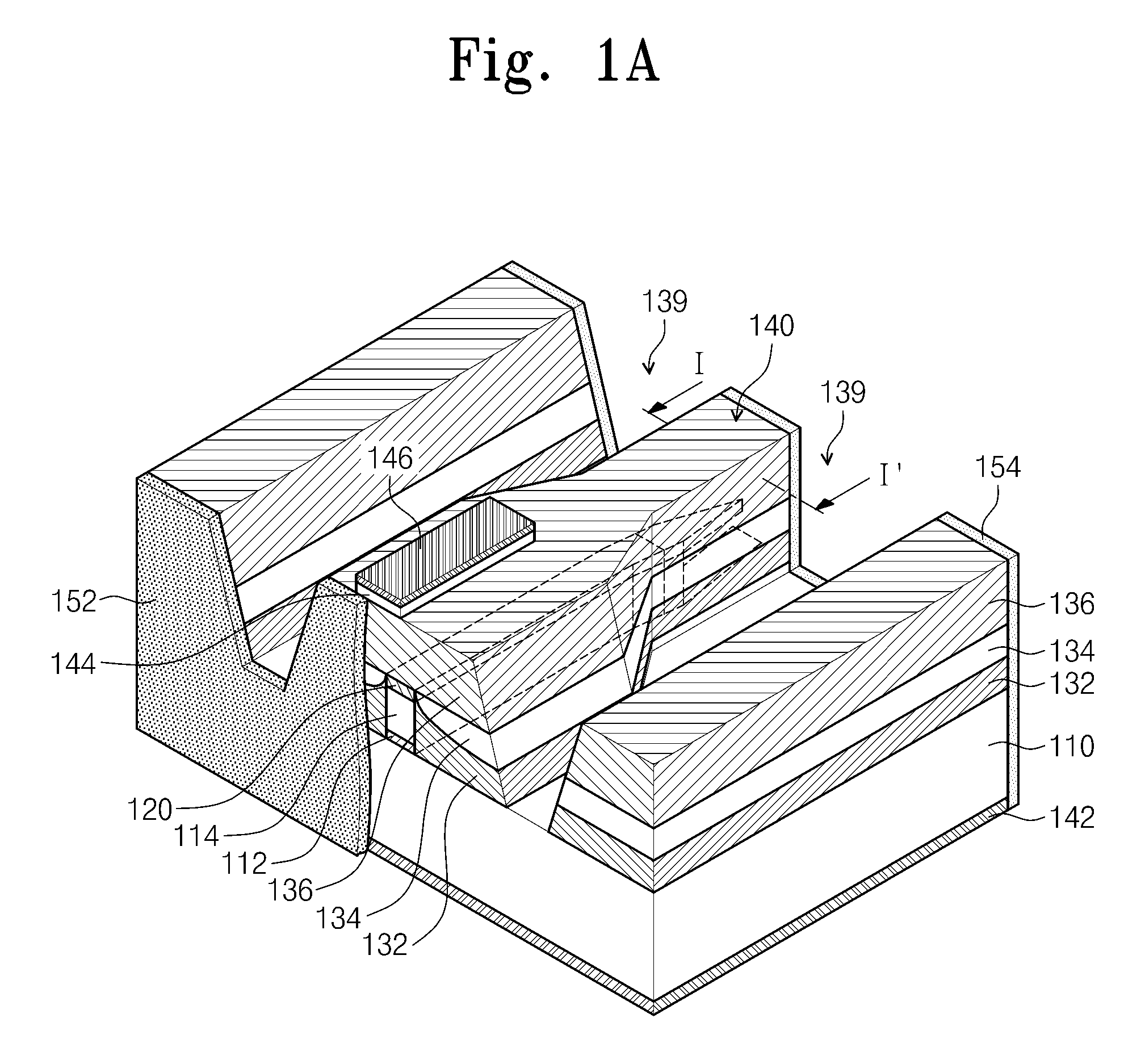
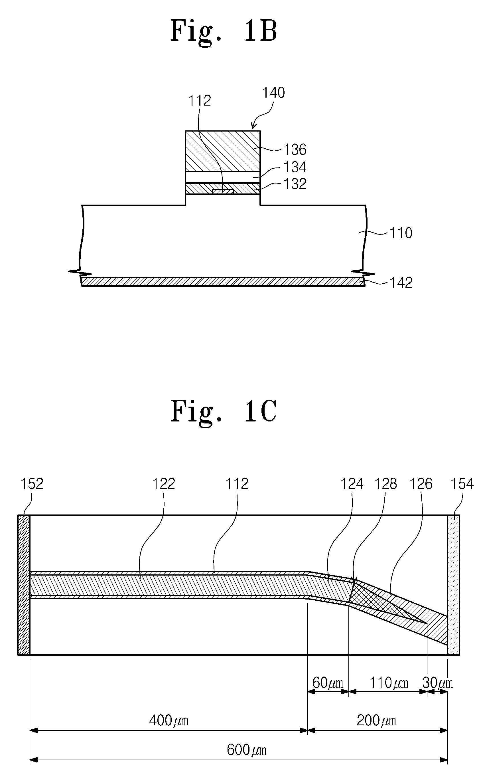
[0044]Preferred embodiments of the present invention will be described below in more detail with reference to the accompanying drawings. The present invention may, however, be embodied in different forms and should not be construed as limited to the embodiments set forth herein. Rather, these embodiments are provided so that this disclosure will be thorough and complete, and will fully convey the scope of the present invention to those skilled in the art. Further, the present invention is only defined by scopes of claims. Like reference numerals refer to like elements throughout.

[0045]In the following description, the technical terms are used only for explain a specific exemplary embodiment while not limiting the present invention. The terms of a singular form may include plural forms unless referred to the contrary. The meaning of “include,”“comprise,”“including,” or “comprising,” specifies a property, a region, a fixed number, a step, a process, an element and / or a component but d...


PUM


Abstract

Provided is an external cavity laser light source. The light source includes a substrate, an optical waveguide, and a current blocking layer. The optical waveguide includes a passive waveguide layer, a lower clad layer, an active layer, and an upper clad layer that are sequentially stacked on the substrate and is divided into regions including a linear active waveguide region, a bent active waveguide region, a tapered waveguide region, and a window region. The current blocking layer was formed an outside of the active layer to reduce leakage current. The linear and bent active waveguide regions have a buried heterostructure (BH), and the tapered waveguide region and the window region have a buried ridge stripe (BRS) structure. The passive waveguide layer a width substantially equal to a maximal width of the tapered waveguide region at least in the bent active waveguide region, the tapered waveguide region, and the window region.

Description

CROSS-REFERENCE TO RELATED APPLICATIONS[0001]This U.S. non-provisional patent application claims priority under 35 U.S.C. §119 of Korean Patent Application No. 10-2009-0024623, filed on Mar. 23, 2009, the entire contents of which are hereby incorporated by reference.BACKGROUND OF THE INVENTION[0002]The present invention disclosed herein relates to an external cavity laser, and more particularly, to a superluminescent diode (SLD) and a reflective semiconductor optical amplifier (R-SOA) that are used as external cavity laser light sources.[0003]There are various light sources of an optical line terminal (OLT) and an optical network unit (ONU), which are used for a wavelength division multiplexing passive optical network (WDM-PON). In the previous paper (Optics Express, Vol. 16, No. 22, pp. 18194-18201), a planar lightwave circuit external cavity laser (PLC-ECL) is disclosed, which is fabricated by a hybrid integration method using an SLD and a polymer waveguide in which a grating are ...

Claims


Application Information

Patent Timeline
Patent Type & Authority Applications(United States)
IPC IPC(8): H01S5/14H01S5/026H01S5/34
CPCH01S5/028H01S5/101H01S5/1014H01S5/2231H01S5/14H01S5/164H01S5/1085H01S5/10H01S5/20H01S5/22
Inventor OH, SU HWANYOON, KIHONGKIM, KISOOOH, DAE KON
Owner ELECTRONICS & TELECOMM RES INST
Why Eureka
Try Eureka