
Oil pan structure for internal combustion engine

a technology for internal combustion engines and oil pans, which is applied in the direction of casings, lubricant level maintenance, lubrication elements, etc., can solve problems such as deterioration of aeration performance, and achieve the effect of reducing aeration (mixed air percentage)

Inactive Publication Date: 2003-05-27
SUZUKI MOTOR CORP
View PDF23 Cites 20 Cited by
  • Summary
  • Abstract
  • Description
  • Claims
  • Application Information

AI Technical Summary

Benefits of technology

Oil dropped from a cylinder block of an engine is returned back to an oil pan after passing around a crankshaft. Since the crankshaft is not moving while an engine is not operating, oil comes down along the cylinder block wall to a first baffle plate, comes into an oil dropping hole on the first baffle plate, which directs the oil towards a bottom of an oil pan, and is returned to the inside of the oil pan. While the engine is operating, much oil seems to be splashed to the crankshaft and circulated around the crankshaft. The oil finally directed to the bottom of the oil pan contains a lot of air bubbles so that it may cause deterioration of aeration performance (oil property endurance to the aeration). Thus, the object of the present invention is to reduce the aeration (mixed air percentage in the oil).
Therefore, the present invention provides the oil pan structure of the engine to keep two oil levels within a certain difference of two chambers partitioned by a second baffle plate in the oil pan in order to reduce the oil level change by vehicle turn and to reduce the aeration at the same time.
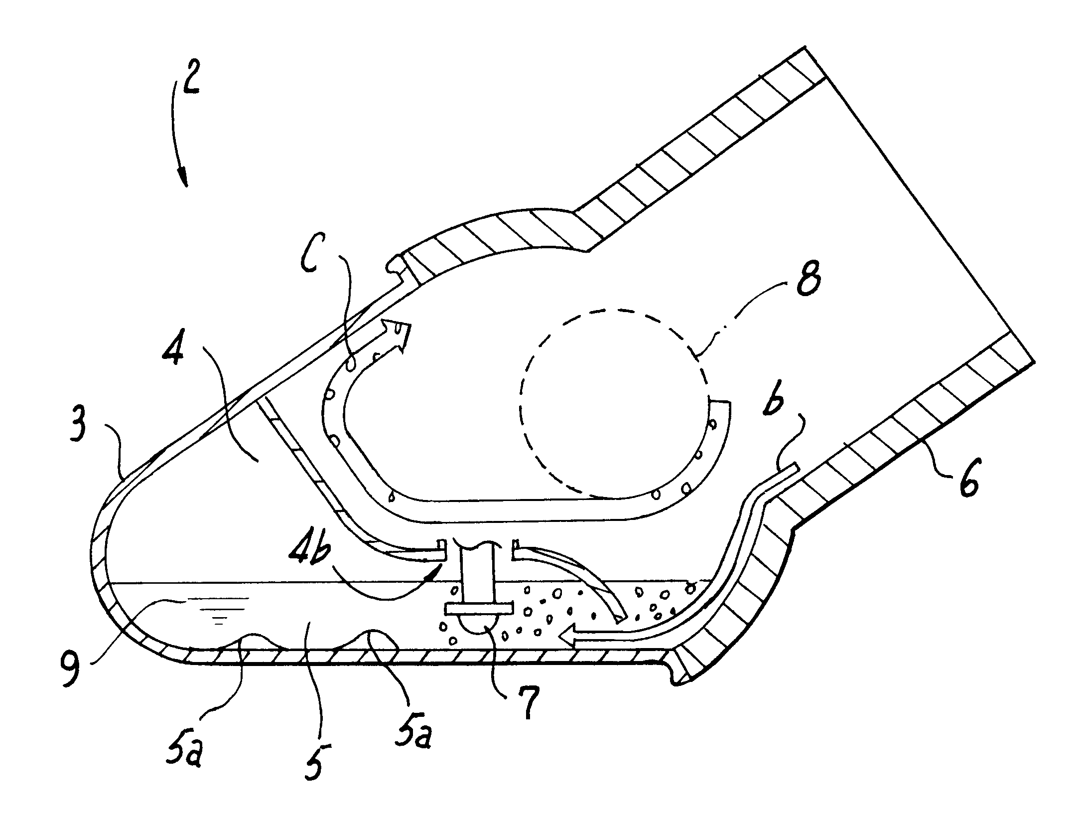
The present invention seeks to achieve the above-mentioned goal and provides the oil pan having a horizontal bottom plate and secured to the engine mounted on the vehicle body such that its cylinder axial line is inclined to the vertical face including the crankshaft axis, comprising: a first baffle plate having a horizontal portion separated with a certain distance from the bottom of the oil pan, the first baffle plate having a first opening directing oil towards the bottom of the oil pan; a second baffle plate disposed vertically between the first baffle plate and the bottom of the oil pan to partition the space into two compartments; and an oil passing passageway disposed in a lower position than the horizontal portion of the first baffle plate so that the oil may pass through the passageway between the two compartments in order to equalize the oil level of each compartment (or chamber).
In accordance with the present invention, the first baffle plate can prevent oil from dropping directly from the cylinder block to the surface of the oil stored in the oil pan so as to reduce generation of air bubbles and it can be possible to accelerate removing mixed air bubbles from the oil in either compartment of the two compartments so as to reduce the aeration.
Since the oil passageway (second opening) equalize oil surface heights in the compartments is formed in a portion near the bottom of the oil pan in the second baffle plate the oil passageway may allow oil having relatively less mixed air bubbles to flow between two compartments so that the aeration is effectively reduced when the oil with less air bubbles flows into the other compartment where an oil pump sucks oil up.
In accordance with the present invention, the oil pan structure further comprises an oil strainer for sucking oil in one of the two compartments and an oil dropping hole (third opening) such that the oil may efficiently be collected and the mixed air bubble may efficiently be removed.

Problems solved by technology

While the engine is operating, much oil seems to be splashed to the crankshaft and circulated around the crankshaft.
The oil finally directed to the bottom of the oil pan contains a lot of air bubbles so that it may cause deterioration of aeration performance (oil property endurance to the aeration).

Method used


Image

  • Oil pan structure for internal combustion engine
  • Oil pan structure for internal combustion engine
  • Oil pan structure for internal combustion engine

Examples


first embodiment

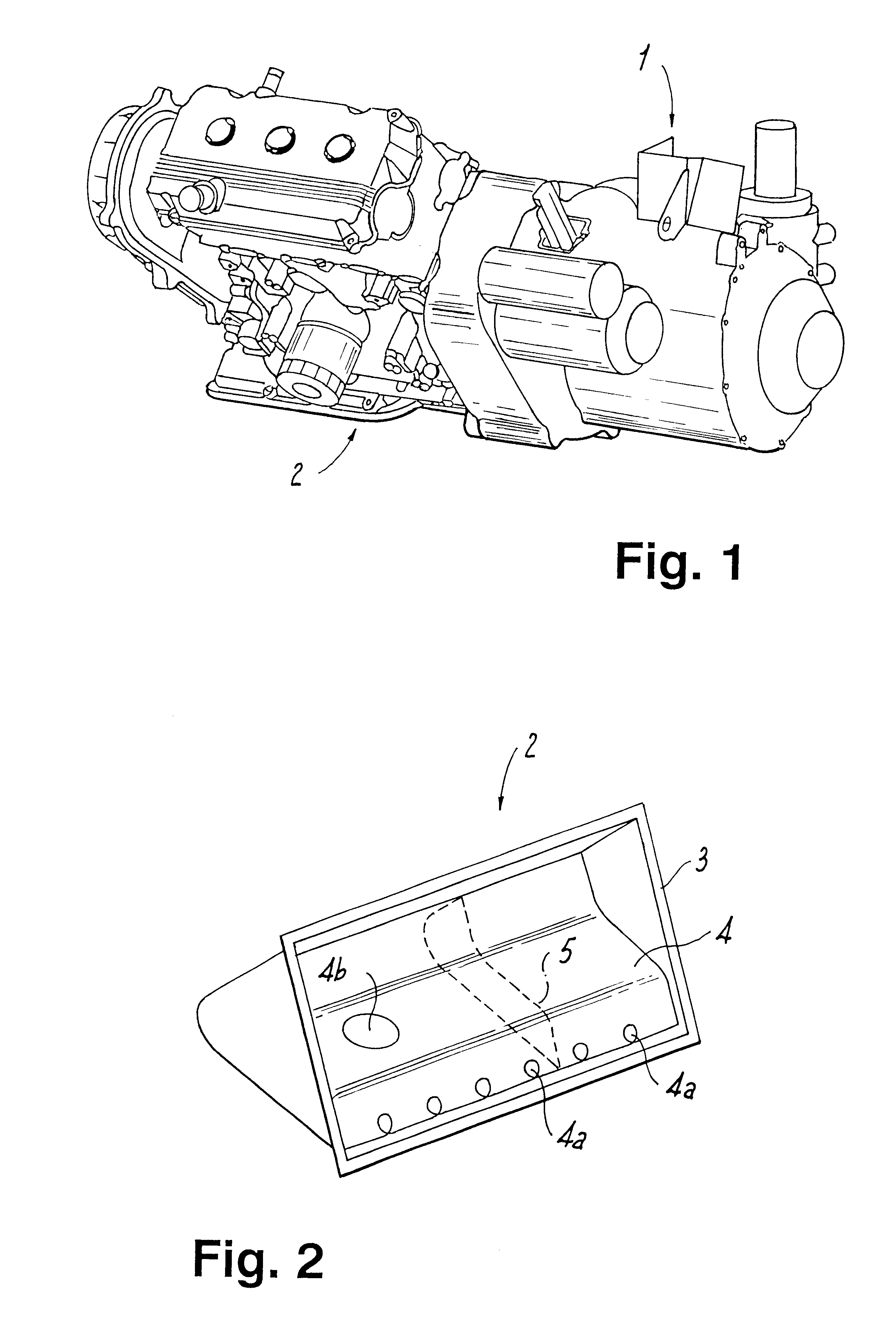
FIG. 2 shows an oil pan 2 of an embodiment of the present invention. The oil pan 2 has a different shape from a regular tray-type oil pan. A housing 3 of the oil pan 2 is formed to have a side view of a triangle as shown in the figure. The housing 3 is a hollow triangular prism with one side face open. Since the oil pan 2 is secured to the engine 1 in such direction as shown in FIG. 2, the bottom face (one of the side faces of the hollow triangular prism, but not the open side face) in FIG. 2, which shows the oil pan 2 with the open side face of the hollow triangular prism facing towards the front, corresponds to the real bottom face, which is horizontal, when the oil pan 2 is fixed on the engine 1. Inside of the housing 3, a first baffle plate 4 is disposed horizontally with a certain distance from the bottom face of the oil pan 2 such that oil having air bubbles after lubricating elements may not drop from a cylinder block or a crank case directly to the surface of oil stored in t...

second embodiment

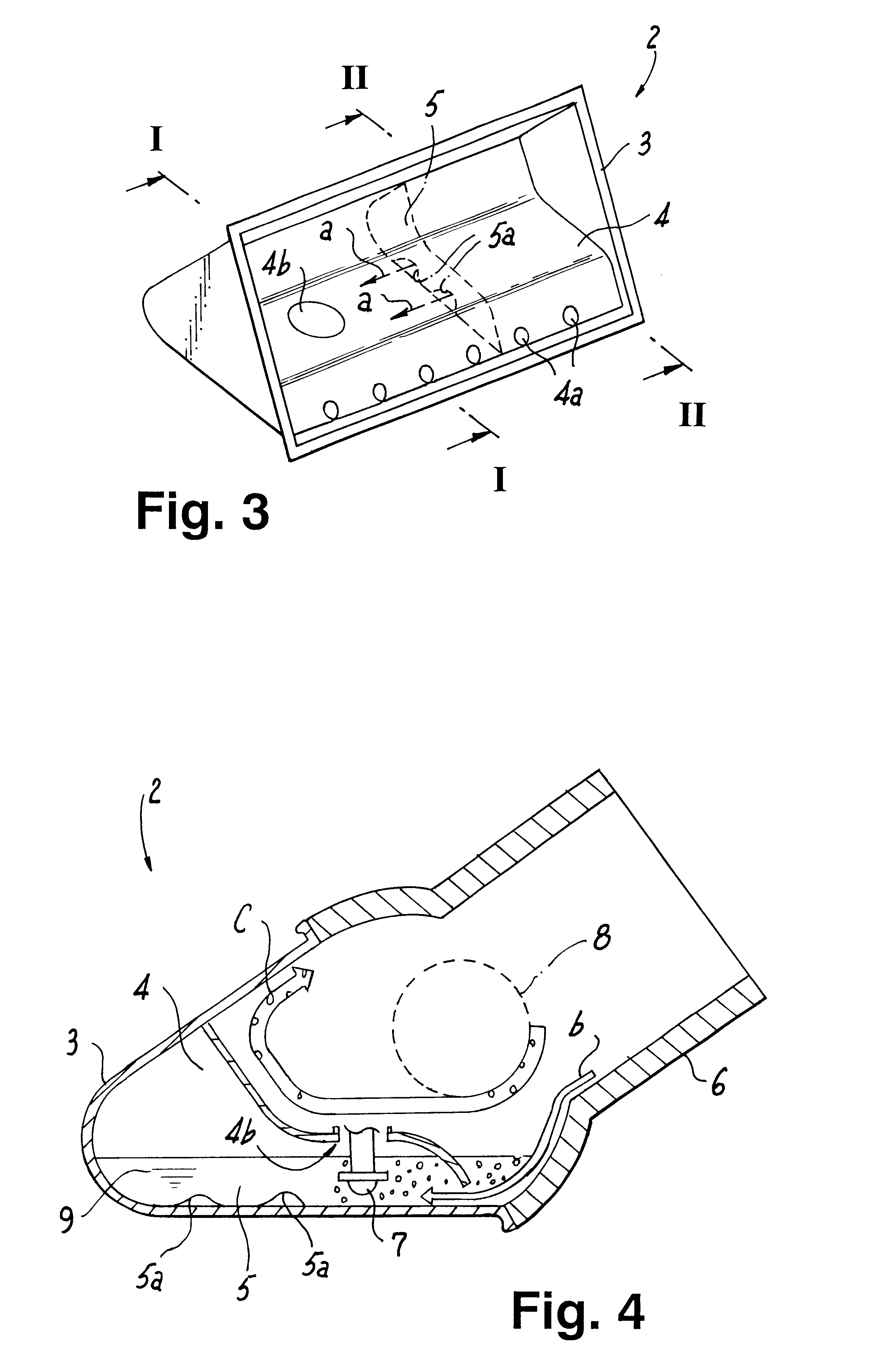
FIG. 3 shows another embodiment of the present invention. FIG. 3 is corresponding to FIG. 2 of the first embodiment and thus has only difference from FIG. 2 that the second baffle plate 5 has openings 5a (second openings) near the bottom of the oil pan2. Since the second baffle plate 5 has openings 5a (second openings), oil may pass through the openings, as indicated by an arrow `a,` between two compartments partitioned by the second baffle plate 5 such that the oil surface height of each compartment may not be very different. Since the openings 5a (second openings) are made near the bottom face of the oil pan 2, mixed air bubbles, which tend to float upper with buoyancy, are hard to pass the openings 5a (second openings). Therefore, the compartment, into which the oil flows through the openings 5a (second openings), stores oil having relatively less air bubbles.

FIG. 4 is an I--I sectional view of FIG. 3 from the left hand side. The figure illustrates how the oil pan 2 is fixed on t...

third embodiment

FIG. 6 shows another embodiment of the present invention, FIG. 7 shows an III--III sectional view of FIG. 6 from the left hand side. FIG. 8 is a IV--IV sectional view of FIG. 6 from the left hand side. These figures are corresponding to FIGS. 3, 4, and 5 of the previous embodiment and are only different in an opening as mentioned below. In the third embodiment, the first baffle plate 4 has an oil dropping hole 4c (third opening) from the cylinder block side over one compartment, where the oil strainer 7 is not disposed, of the two compartments partitioned by the second baffle plate 5. Thus, with the hole 4c (third opening), as shown in FIG. 8, most oil circulating clockwise around the crankshaft 8 in accordance with the crankshaft 8 rotation drops through the hole 4c (third opening) to the bottom of the oil pan 2. Then, oil with relatively large amount of mixed air bubbles is stored in the compartment in which the oil strainer 7 is not disposed, flows to the other compartment throug...


PUM


Abstract

An oil pan (2) fixed on an engine mounted on a vehicle with an inclination angle has a first baffle plate (4), a portion of which is horizontally disposed, in the inside of the oil pan, a second baffle plate (5) disposed vertically between the first baffle plate (4) and the bottom of the oil pan (2) such that said second baffle plate (5) partitions the space into two compartments, and an oil passageway between the two compartments. Since the oil passage way reduces mixed air bubbles in the oil when the oil flows through the passageway, either compartment has less mixed air bubbles such that the oil surface levels in the two compartments may be equalized and that the aeration may be reduced.

Description

The present invention relates to an oil pan structure of an engine mounted with an axial line of a cylinder of the engine inclined to the vertical direction, and more particularly to the oil pan structure of the engine mounted with a great inclination angle.Since a commercial vehicle such as a truck cannot have so large engine compartment as a passenger car does, the commercial vehicle may hold its engine under the floor. In such arrangement, the engine is mounted on the vehicle with an axial line of a cylinder of the engine inclined to the vertical direction (so-called a slant engine). Since the engine is mounted in such a manner, its oil pan, which is located at the lowest position, has a different shape from the usual tray-like structure. Tokukai No. Hei 5-86826, for example, discloses an oil pan, of which cross-section is almost a triangle. The specification discloses the invention of the oil pan structure, which includes two chambers (or compartments) with different oil levels ...

Claims


Application Information

Patent Timeline
Patent Type & Authority Patents(United States)
IPC IPC(8): F01M11/00F01M11/06F02F7/00
CPCF01M11/0004F01M2011/0041F01M2011/0033
Inventor SUGIURA, HISAHITO
Owner SUZUKI MOTOR CORP
Learn More