Parallel A2O-MBR denitrifying phosphorus removal method

A nitrification, polyphosphorus and denitrification, parallel technology is applied in the field of activated sludge process sewage biological treatment process, which can solve the problems of reduced impact load capacity, consumption, and high nitrate concentration, and achieves good dynamism, increased control, and reduced land occupation effect

Inactive Publication Date: 2011-07-20
TIANJIN POLYTECHNIC UNIV
View PDF3 Cites 21 Cited by
  • Summary
  • Abstract
  • Description
  • Claims
  • Application Information

AI Technical Summary

Problems solved by technology

This results in higher nitrate concentrations in the effluent and return sludge
If there is more nitrate in the anaerobic zone, the denitrifying bacteria will use organic matter as the electron donor for denitrification, consume the organic carbon source in the influent, affect the synthesis of anaerobic product PHB, and then affect the subsequent phosphorus removal effect, forming vicious circle
[0005] (2) Constraints of water effluent by gravity sedimentation
However, this has caused great constraints to the combination of anaerobic, anoxic and aerobic in the process, so the traditional nitrogen and phosphorus removal process is mostly anaerobic-anoxic-aerobic-sedimentation tank
Moreover, the settling performance of the secondary settling tank will seriously affect the quality of the effluent water, reducing the impact load resistance of the system
[0007] (3) Contradiction between supply and demand of nitrate nitrogen
In order to achieve a better denitrification effect, a larger internal reflux ratio is required, which increases the operating cost of the system

Method used


Image

  • Parallel A2O-MBR denitrifying phosphorus removal method
  • Parallel A2O-MBR denitrifying phosphorus removal method

Examples


Embodiment Construction

[0017] Below in conjunction with accompanying drawing and embodiment the present invention is described in detail:

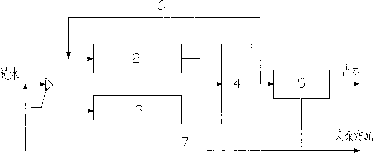
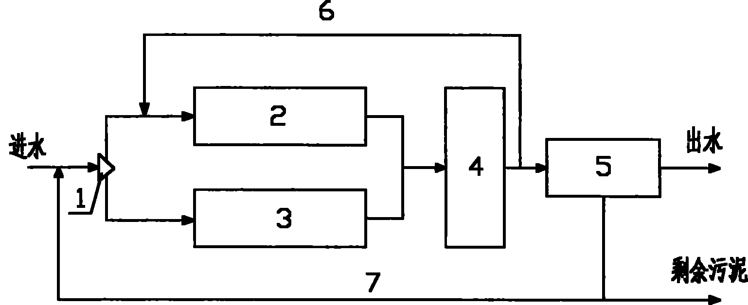
[0018] The present invention is composed of water distribution inlet, anaerobic pool, aerobic pool, anoxic pool, mixed liquid return system, sludge return system and MBR pool. The anaerobic pool and aerobic pool are connected in parallel, and then enter the anoxic pool together. , and finally through the membrane water. The sewage first passes through the water distribution well to distribute water for the anaerobic pool and the aerobic pool. The water distribution well adopts the overflow weir type, and the weir plate is adjustable, so as to adjust the influent flow of the anaerobic pool and the aerobic pool; the sewage entering the anaerobic pool and the return flow The sludge is mixed to provide carbon source for the phosphorus-accumulating bacteria in the anaerobic tank for anaerobic phosphorus release; another part of the sewage enters the aerobic zone, and...


PUM


Abstract

The invention belongs to the technical field of sewage treatment, and relates to a parallel anaerobic-anoxic-oxic (A2O)-membrane bioreactor (MBR) denitrifying phosphorus removal method. Adopted devices comprise an oxic tank, an anaerobic tank, an anoxic tank and a membrane tank, wherein the oxic tank is connected in parallel with the anaerobic tank; sewage to be treated and external reflux sludge are mixed in a distribution well and flow into the oxic tank and the anaerobic tank according to a proper proportion respectively, and internal reflux mixed liquid which reflows from the anoxic tank also flows into the oxic tank simultaneously; sewage which flows out of the oxic tank and sewage which flows out of the anaerobic tank are mixed and flow into the anoxic tank together for denitrifying phosphorus removal; and the sewage enters an MBR tank for sludge and water separation, and a part of residual sludge serves as the external reflux sludge to be fed into the distribution well. The parallel A2O-MBR denitrifying phosphorus removal method can be used for the new construction and modification engineering of a biological denitrifying phosphorus removal sewage plant, the volume and the aeration amount of an aeration tank can be reduced, and a secondary sedimentation tank can be eliminated simultaneously, so that the floor space of an urban sewage plant is reduced.

Description

technical field [0001] The invention belongs to the technical field of sewage treatment, and relates to an activated sludge sewage biological treatment process. Background technique [0002] Biological phosphorus and nitrogen removal A 2 The O process has only been developed for more than 20 years, but because of its simple process, it can take into account the removal of N and P and has a good effect, so the development is relatively rapid. With the continuous improvement of sewage discharge requirements, its treatment effect can no longer meet the discharge standards. The reason is related to the inherent shortcomings of the process itself, such as the different sludge ages, releases and releases of nitrifying bacteria, denitrifying bacteria and phosphorus Phosphorus and denitrification competition for carbon sources, etc. [0003] (1) Insufficient carbon source [0004] In the traditional nitrogen and phosphorus removal process, different bacteria are used for nitrogen...

Claims


Application Information

Patent Timeline
Patent Type & Authority Applications(China)
IPC IPC(8): C02F9/14
Inventor 王亮张明虎张宏伟吴晓娜
Owner TIANJIN POLYTECHNIC UNIV
Why Eureka
Try Eureka