Apparatus for directing fluids through a filter system

a filter system and apparatus technology, applied in the direction of filtration separation, separation process, treatment involving filtration, etc., can solve the problems of disadvantageous course, expensive installation of gravel support layers, time-consuming installation, etc., and achieve the effect of convenient water evacuation and convenient attachmen

Inactive Publication Date: 2003-05-27
RG DELAWARE
View PDF28 Cites 31 Cited by
  • Summary
  • Abstract
  • Description
  • Claims
  • Application Information

AI Technical Summary

Benefits of technology

Still a further object of a preferred embodiment of the present invention is to provide a fluid distribution system that permits an air conduit to be readily attached to an underdrain.
Yet another object of the present invention is to provide a fluid distribution system which includes an air conduit having means for facilitating evacuation of water from the air conduit.

Problems solved by technology

This of course is disadvantageous.
However, gravel support layers have a number of disadvantages.
Specifically, gravel support layers are expensive and time consuming to install.
Further, gravel support layers consume a significant portion of the filter chamber thus reducing the filtering capacity of the bed.
Also, gravel support layers are subject to being upset when uncontrolled air enters the filter bed due to improper installation of the air system or operator error.
At the extreme temperatures necessary to reactivate the granular activated carbon the gravel can explode damaging the furnace.
This conventional means of securing the porous plate to the underdrain block has significant drawbacks.
These conventional fasteners increase the cost of the system from both a materials and labor stand point.
Further, if the porous plate needs to be replaced a laborer would be required to removal all of the numerous fasteners before such could be accomplished.
Moreover, conventional fasteners could damage the porous plate requiring its removal.
In addition, a direct connection of the porous plate to the underdrain block without sufficient offset would likely lead to maldistribution of the fluid.
Another significant disadvantage of prior developments is that an existing underdrain could not be satisfactorily retrofitted with a porous plate thereby obviating the need for one or more gravel support layers.
Further, prior developments lacked the ability to readily retrofit numerous different types of underdrains with a porous plate to thereby obviate the need for one or more gravel support layers.
Such underdrain systems have significant drawbacks.
Specifically, because of the conflict between the flow rates of liquids and gases, upper limits must unnecessarily be imposed minimizing the flexibility in setting different ranges of flow rates for liquids and gases.
Further, common discharge passages for liquids and gases result in uneven discharge of the air bubbles resulting in undesirable maldistribution.
Some previously known air scour systems have also suffered from the disadvantage of maldistribution owing to incomplete evacuation of water from the air conduit.
The problem of incomplete evacuation of water is often experienced where the air conduit has not been installed correctly.
In such circumstances, the exit or discharge openings on the low side of the air conduit often remain blocked by water preventing proper distribution of air to the filter bed to adequately clean the same.
Previously known combined air and liquid distribution systems utilizing shared conduits have experienced uncontrolled releases of air which can lead to significant problems.
Specifically, systems using shared conduits are likely to experience rapid introduction of air or water flow.
This rapid introduction of flow can create a wave action resulting in fluctuation of the interfaces which can expose the water metering orifices to air flow resulting in gross maldistribution.

Method used


Image

  • Apparatus for directing fluids through a filter system
  • Apparatus for directing fluids through a filter system
  • Apparatus for directing fluids through a filter system

Examples


Embodiment Construction

The preferred forms of the invention will now be described with reference to FIGS. 1-21. The appended claims are not limited to the preferred embodiments and no term used herein is to be given a meaning other than its ordinary meaning unless accompanied by a statement that the term "as used herein is defined as follows".

FIGS. 1 Through 4

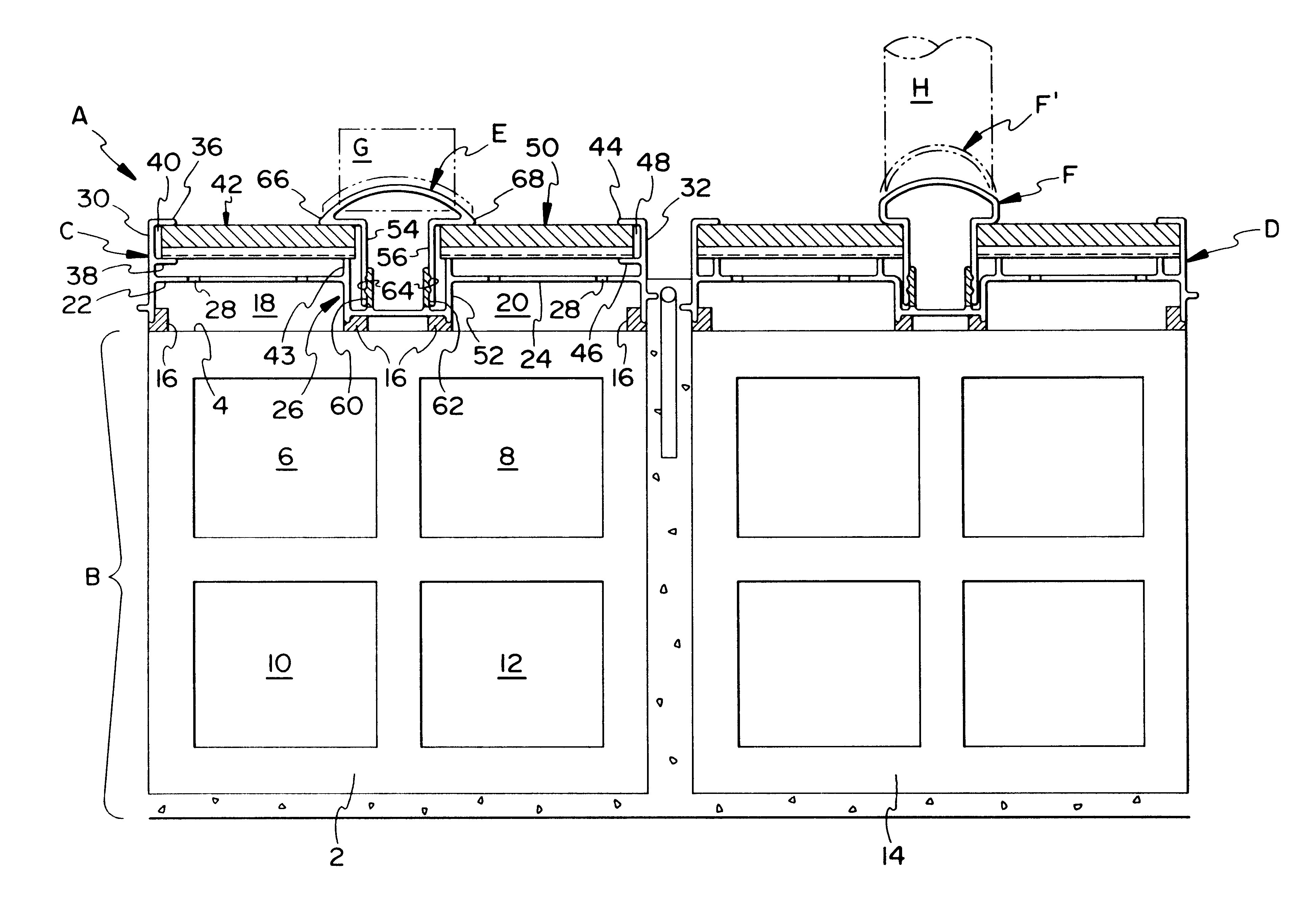
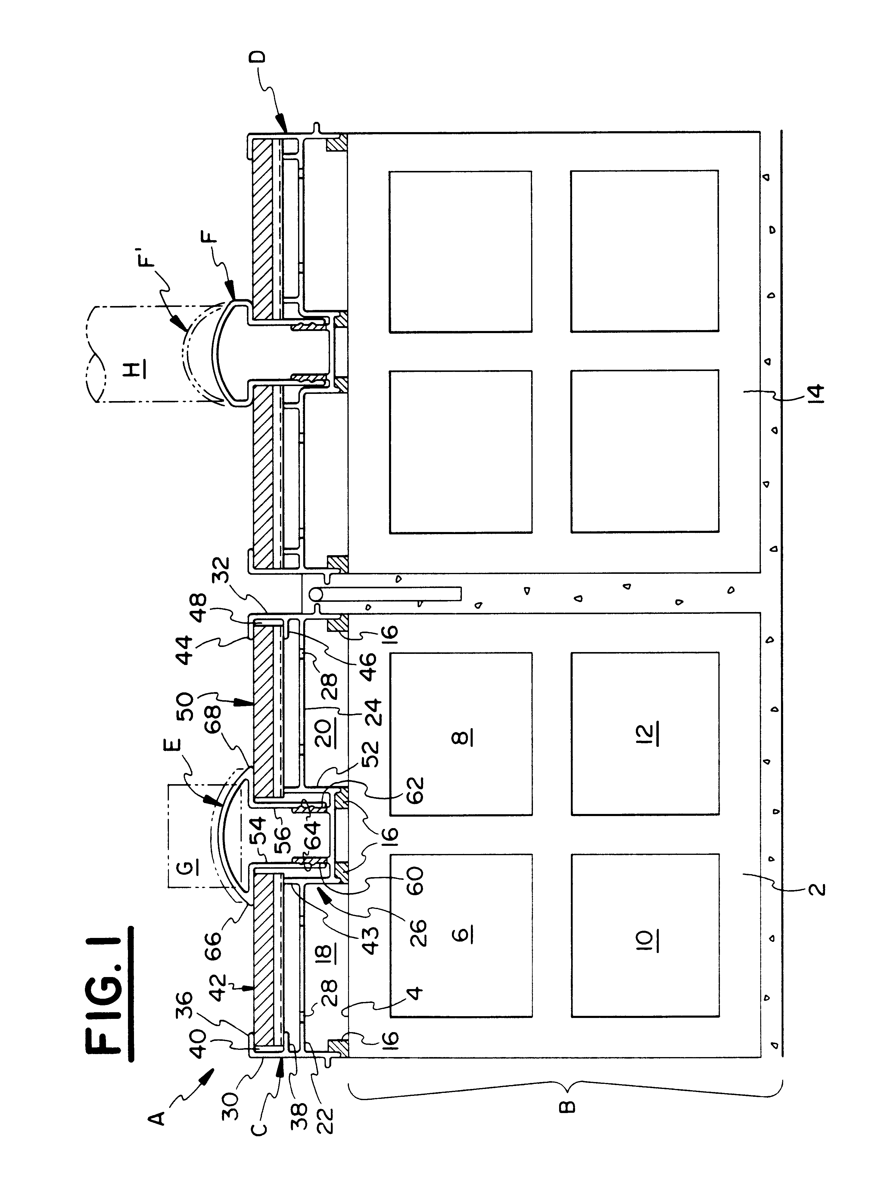
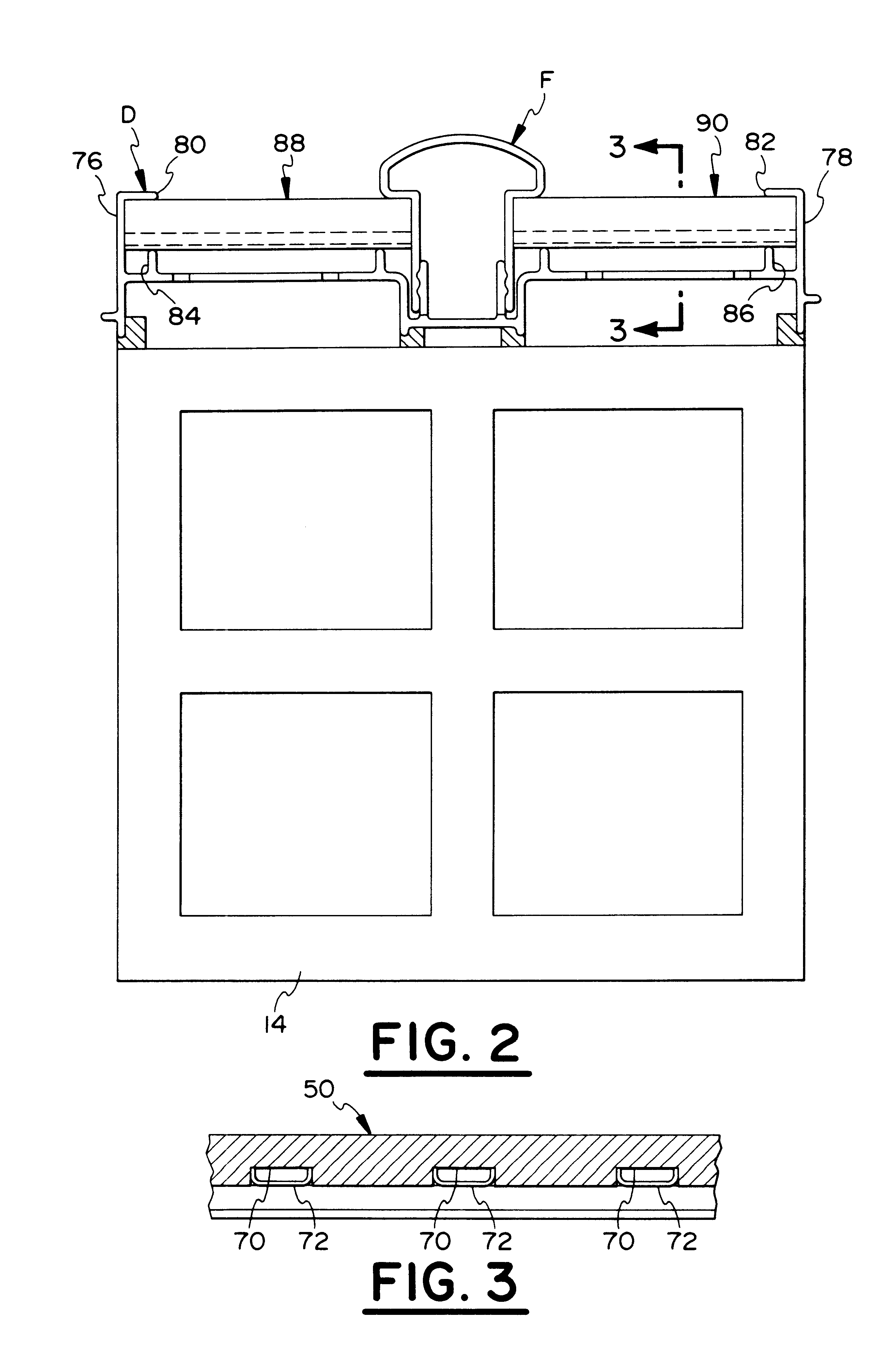
Referring to FIGS. 1 through 4, a fluid distribution system A is depicted. The fluid distribution system includes an existing underdrain B, a pair of underdrain caps C and D and a pair of air conduits E and F. An air supply connection G is secured to the air distribution conduit E in a fluid tight manner. An air supply connection H is secured to the air distribution conduit F in a fluid tight manner.

The existing underdrain includes a plurality of rows of underdrain blocks which are positioned on or adjacent the bottom of the filter. Only two rows are depicted in FIG. 1. The first row 2 of clay tile underdrain blocks are disposed beneath the underdrai...


PUM

PropertyMeasurementUnit
sizeaaaaaaaaaa
timeaaaaaaaaaa
temperaturesaaaaaaaaaa

Abstract

A fluid distribution system for directing fluids through a filter system. The fluid distribution system ensures proper distribution of fluids during the process of filtering as well as the process of washing a filter bed. The fluid distribution system may be used with numerous filter systems including but not limited to an upflow filter, a downflow filter, a combined upflow/downflow filter and/or multiple downflow filters connected in series.

Description

The present invention includes one or more devices for directing fluids (i.e., a liquid and / or a gas) through a filter system for filtering water and / or wastewater. The filter system includes but is not limited to an upflow filter, a downflow filter, a filter system having a combined upflow filter and a downflow filter and / or a filter system having multiple (i.e., more than one) downflow filters connected in series.Various systems have been developed to filter water and wastewater. Typical filter systems include but are not limited to an upflow filter, a downflow filter, a combined upflow filter and a downflow filter and multiple downflow filters connected in series. The term upflow filter is given to a filter in which the liquid or influent to be filtered is directed in an upward path to remove impurities. Conversely, a downflow filter is a filter in which the influent is directed in a downward path to remove impurities. In a combined upflow / downflow filter, influent is directed up...

Claims


Application Information

Patent Timeline
Patent Type & Authority Patents(United States)
IPC IPC(8): B01D24/24B01D24/02C02F1/28C02F1/00
CPCB01D24/24B01D24/38B01D24/4631C02F1/001Y10T29/49817C02F2303/16C02F1/28
Inventor ROBERTS, R. LEEADDISON, MARK KEVIN
Owner RG DELAWARE
Why Eureka
Try Eureka