Device for heating shrinkable sleeves

a shrinkable and device technology, applied in the field of devices for heating shrinkable sleeves, can solve the problems of degrading mechanical properties, slow control of heating or shrinking process, and normal cooling process taking a long tim

Inactive Publication Date: 2003-05-27
TELEFON AB LM ERICSSON (PUBL)
View PDF23 Cites 13 Cited by
  • Summary
  • Abstract
  • Description
  • Claims
  • Application Information

AI Technical Summary

Benefits of technology

It is another object of the invention to provide a resistance element for a heating device for shrinkable sleeves, which has a simple mounting attachment and can be easily electrically contacted.
Thus generally, a resistance element for a device for shrinking shrinkable sleeves can comprise a thin, elongate electrical conductor or wire extending in a zigzag path and bent to a tunnel shape. The shrinkable sleeve is intended to be placed in the region of the resistance element that corresponds to approximately the geometric axis of the upper semi-cylindrical portion of the tunnel shape. The mounting of the resistance element is only made by a few thin pins, located at the front and rear sides of the element and intended to be placed in corresponding recesses in a lid in the device, most of the pins being connected to the conductor extending in zigzag through narrow connecting portions. In addition, the rear pins have portions intended for contact with electrically conducting, elastic contact pins, with which the resistance element comes in contact, when the lid is folded down to execute the very heating and shrinking operation. The open and freely suspended design of the resistance element having only small contact areas to the lid results in that the resistance element can be rapidly heated and thereafter be rapidly cooled implying the same conditions to be true also for the shrinkable sleeve placed inside the resistance element and also having the effect that a shrinking operation can be executed within a minimum time period.

Problems solved by technology

In the heating it must be carefully observed that no air is left inside the shrinkable sleeve, since it will necessarily degrade the mechanical and protecting function of the sleeve.
Such a system results in that the heating or shrinking process has a slow control since also the cradle must be heated.
The cooling process normally takes a fairly long time, since both the sleeve and the cradle must be allowed to cool, and furthermore they are to some extent enclosed by other elements making the cooling not very efficient.
When using such methods often the final cooling of the protective sleeve is the time limiting portion of the welding process, the other steps of which are executed rather quickly, and this can be experienced as disturbing by many users.

Method used


Image

  • Device for heating shrinkable sleeves
  • Device for heating shrinkable sleeves
  • Device for heating shrinkable sleeves

Examples


Embodiment Construction

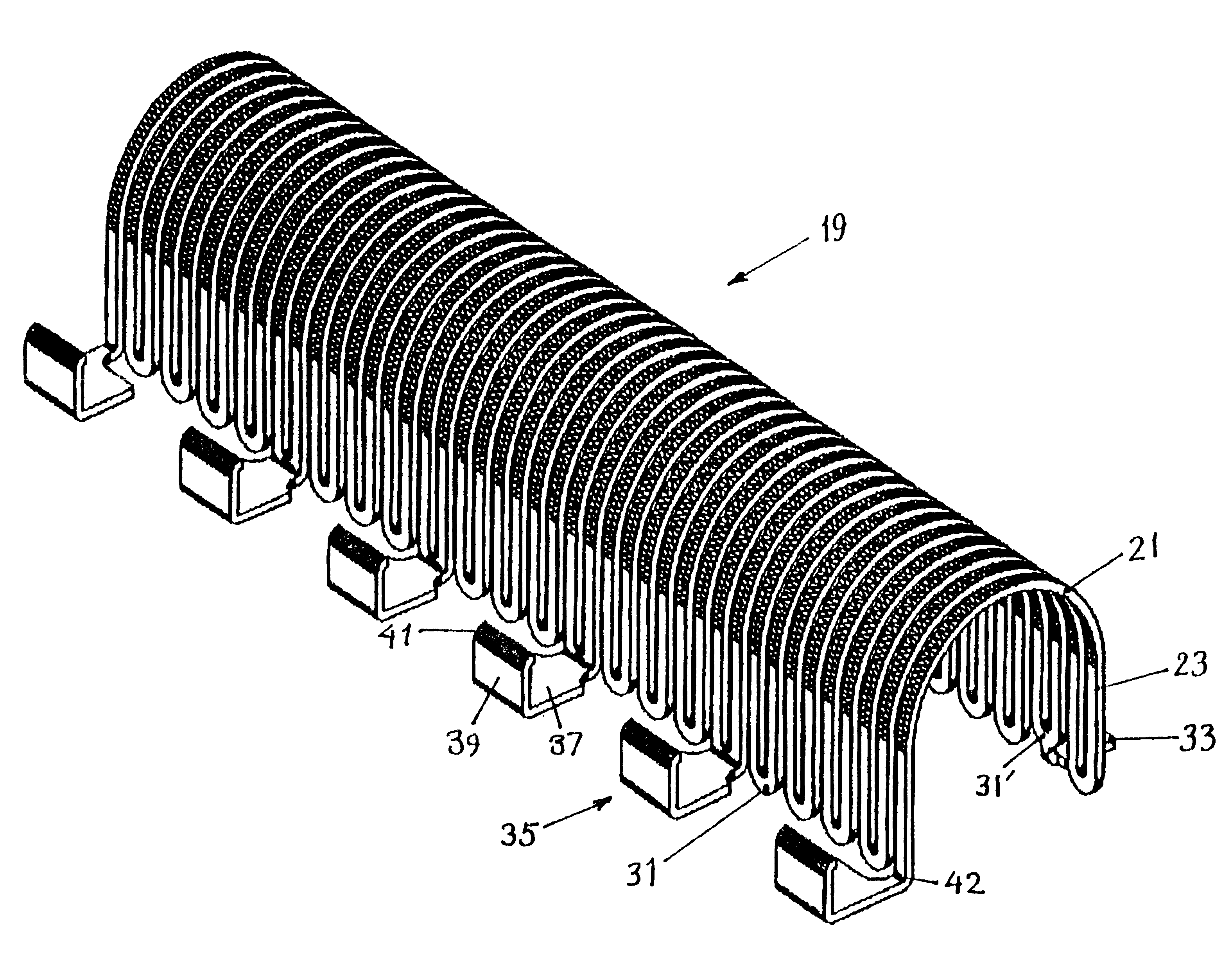
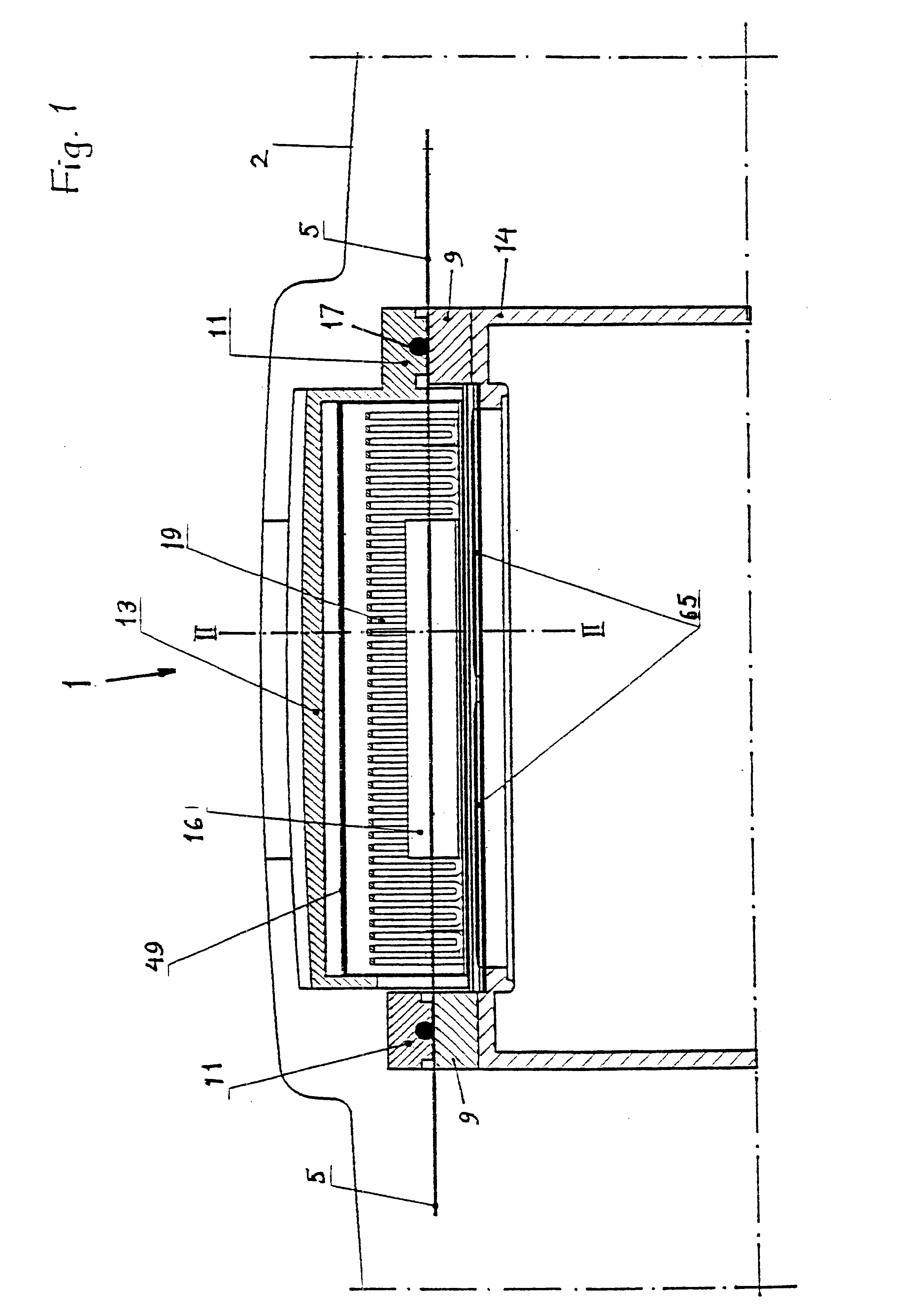
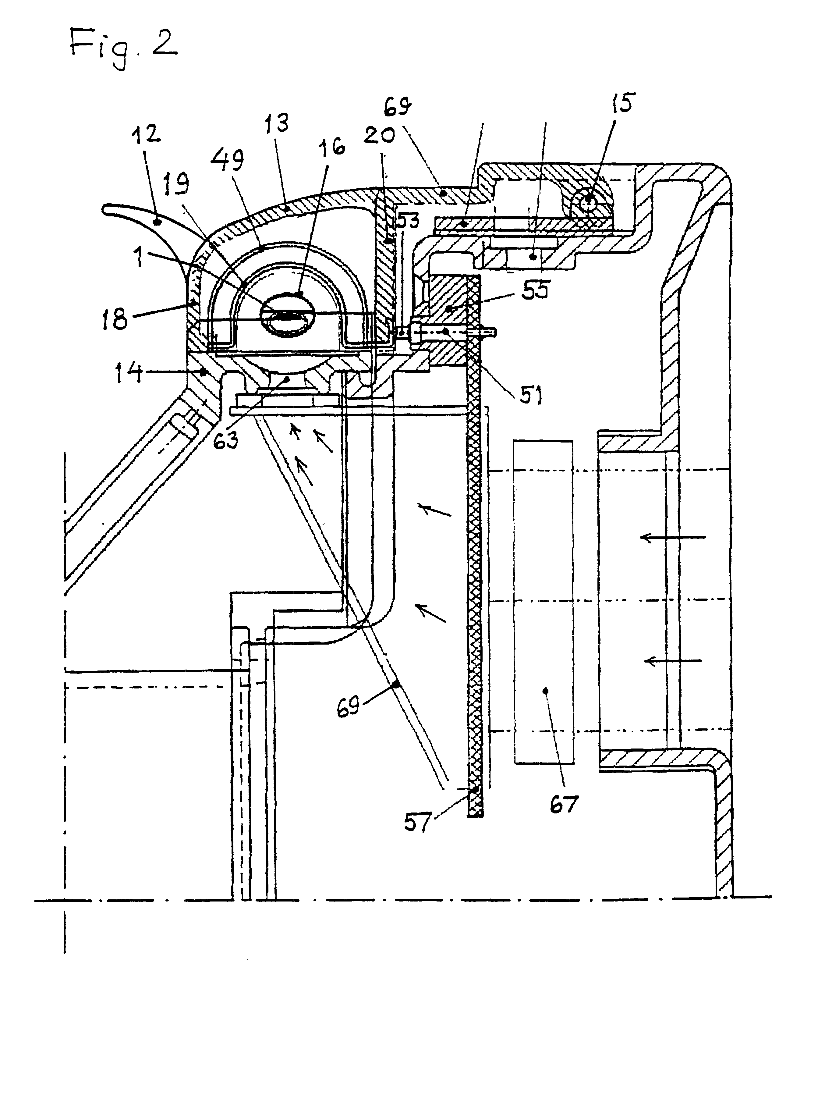
In FIG. 1 a cross-sectional view in the longitudinal direction of a heating device 1, that is closed or folded together, is shown which is intended for shrinkable sleeves placed over a splice position of an optical fiber or, as will be assumed hereinafter, an optical ribbon fiber. The heating device 1 is housed in an automatic fiber splicing device, only the profile of the casing of which being shown at 2. A spliced optical ribbon fiber 5 placed in the heating device, in FIG. 1 seen from the side in a direction parallel to the large surfaces thereof, rests only on upper, upwards facing surfaces of lower support blocks 9 at the end surfaces of the device and is firmly retained in contact with these support surfaces by downwards facing and downwards pressing surfaces of upper support blocks or gripping arms 11 placed at the end surfaces of a lid 13, which is shown in a folded-down state in the figures. The lid 13 is at its rear part rotatably mounted by shaft 15 to a fixed support par...


PUM

PropertyMeasurementUnit
areaaaaaaaaaaa
resistanceaaaaaaaaaa
heating resistanceaaaaaaaaaa

Abstract

A resistance element (19) for a device for shrinking shrinkable sleeves comprises an elongate electrical conductor extending in a zigzag pattern and bent to a tunnel shape. The shrinkable sleeve including for example an optical fiber enclosed therein is placed in that region of the resistance element (19), which corresponds to approximately the geometric axis of the upper semi-cylindric portion of the tunnel shape. The resistance element (1) has attachment pins (33) and contact and attachment pins (35) at its front and rear sides respectively intended to be placed in corresponding recesses in a lid of the device. The rear contact and attachment pins (35) have portions (39) intended for contact with elastic, electrically conducting contact pins with which the resistance element (19) comes in contact, when the lid is folded down to perform the shrinking operation. The open and freely suspended design of the resistance element (19) including only small contact areas to the lid result in that the resistance element can be rapidly heated and thereafter rapidly cooled implying that a shrinking operation can be executed in a minimum of time.

Description

The present invention relates to a device for heating a sleeve which when heated can shrink, for example to produce such a shrinking, when the sleeve is applied to reinforce a splice region between optical fibers or optical ribbon fibers or similar products.BACKGROUND OF THE INVENTION AND PRIOR ARTSleeves which are shrinkable by heat are often used to protect joints between electrically conducting wires and cables and between optical fibers, for example for individual fibers or ribbon fibers used in the telecommunication technology. When used, such a sleeve is applied over an end of a line, e.g. a ribbon fiber, thereafter the line is spliced to another line, the shrinkable sleeve is placed over the splice and finally the shrinkable sleeve is heated making it shrink and firmly grip around the lines, in particular around the splice region and over adjacent isolation or surface layers for signal conductors. In the heating it must be carefully observed that no air is left inside the shr...

Claims


Application Information

Patent Timeline
Patent Type & Authority Patents(United States)
IPC IPC(8): B29C61/00G02B6/38H05B3/10B29C63/42B29C63/38G02B6/255
CPCB29C61/00H05B3/10G02B6/2558B29C63/42B29L2011/0075
Inventor KARACSONY, ISTVANSTROM, JOAKIMSUNDSTROM, BERNT
Owner TELEFON AB LM ERICSSON (PUBL)
Why Eureka
Try Eureka