Doctor roller apparatus

a technology of rollers and rollers, applied in the field of rollers, can solve problems such as the disadvantage of associated outlay in production and stockkeeping

Inactive Publication Date: 2003-06-03
MANROLANAD AG
View PDF9 Cites 1 Cited by
  • Summary
  • Abstract
  • Description
  • Claims
  • Application Information

AI Technical Summary

Benefits of technology

The metering of application medium on the printing machine roller, in particular of printing ink on an ink applicator roller, takes place by means of the doctor roller apparatus according to the invention in a self-regulating manner. For example, when the printing ink requirement on the ink applicator roller is very low, because the latter has a high proportion of ink-repelling surfaces, only a small part of the application medium transported by the doctor roller remains adhering to the ink applicator roller, while the rest is conveyed back into the clearance in which a higher pressure is then established. This pressure prevails on the outlet side at the pressure-regulating valve which thereupon restricts the further inflow of printing ink in order to lower the pressure in the clearance. As a result of the sliding mounting of the doctor roller due to the printing ink forming a hydrodynamic lubricating film in the clearance, a kind of consumption lubrication occurs, in which excess printing ink is automatically conveyed back into the clearance by the doctor roller. This results in a closed system with a low-loss ink circulation and the use of only a small amount of solvent. The application, metering and smoothing of the ink on the ink applicator roller are carried out advantageously by means of a single unit.
On account of the double function of the clearance which gives rise, on the one hand, to a sliding mounting for the doctor roller and, on the other hand, to a transport duct for the printing ink, the doctor roller apparatus according to the invention has an extremely compact build. A short inking zone is consequently obtained, with the result that the outlay in cleaning terms is reduced. Since there is in the clearance a sliding film consisting of printing ink, the mounting of the doctor roller has some elasticity, so that axial errors, unavoidable in practice, between the doctor roller and the ink applicator roller can be compensated. Thus, advantageously, a surface pressure which is constant over the axial length can be achieved between the doctor roller and the ink applicator roller. Finally, the doctor roller apparatus according to the invention can be used for different circumferences and types of printing machine rollers.
According to a preferred embodiment, the working surface of the doctor roller is provided on its ends with helical conveying grooves oriented so that, when the doctor roller is driven, printing ink located at the lateral ends of the clearance can be conveyed to the middle of the doctor roller. Application medium is thereby prevented from escaping laterally from the clearance.

Problems solved by technology

To vary the metering, a different doctor roller with an appropriately adapted engraving must be used, this being a disadvantage in view of the associated outlay in terms of production and stockkeeping.

Method used


Image

  • Doctor roller apparatus
  • Doctor roller apparatus
  • Doctor roller apparatus

Examples


Embodiment Construction

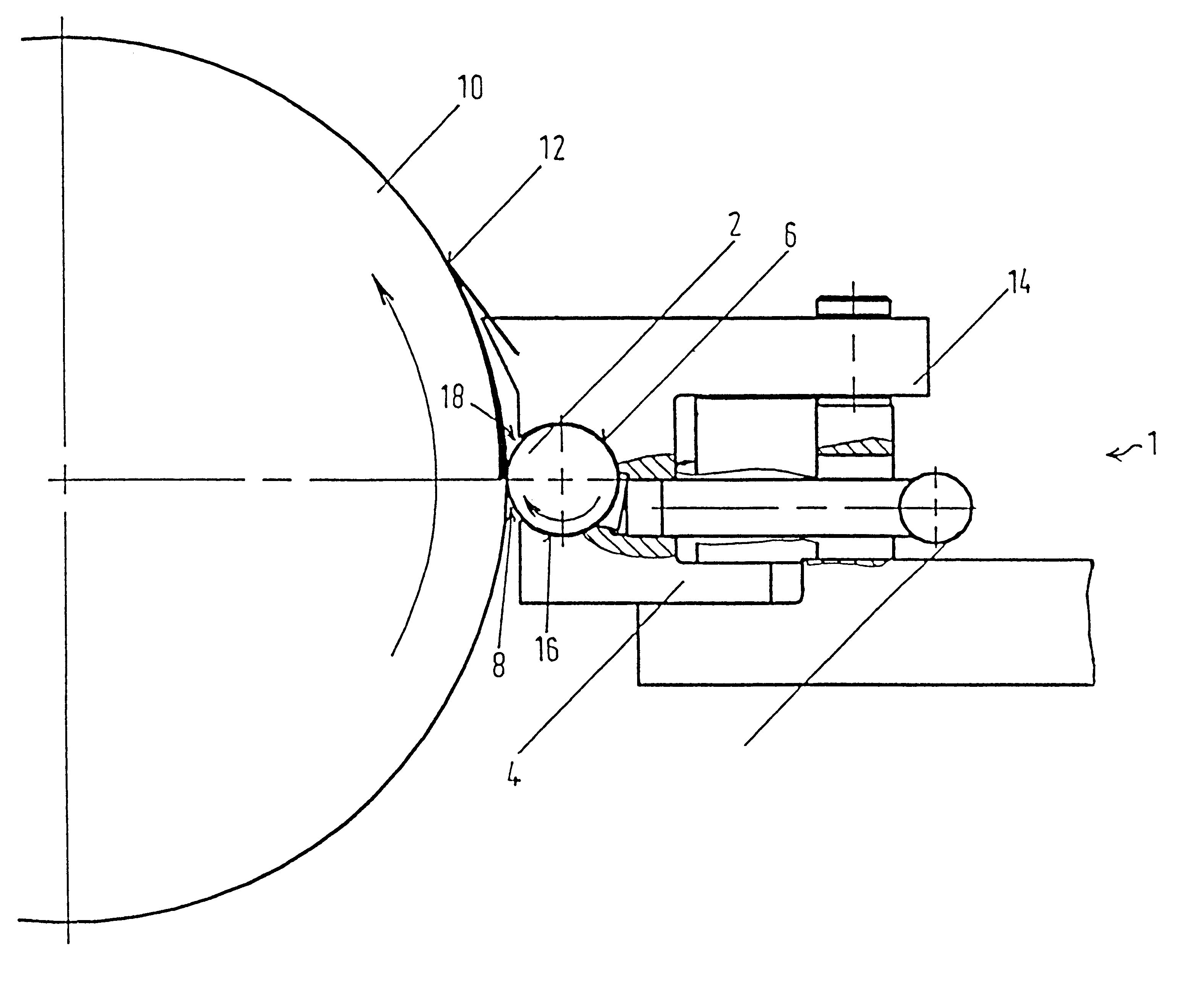
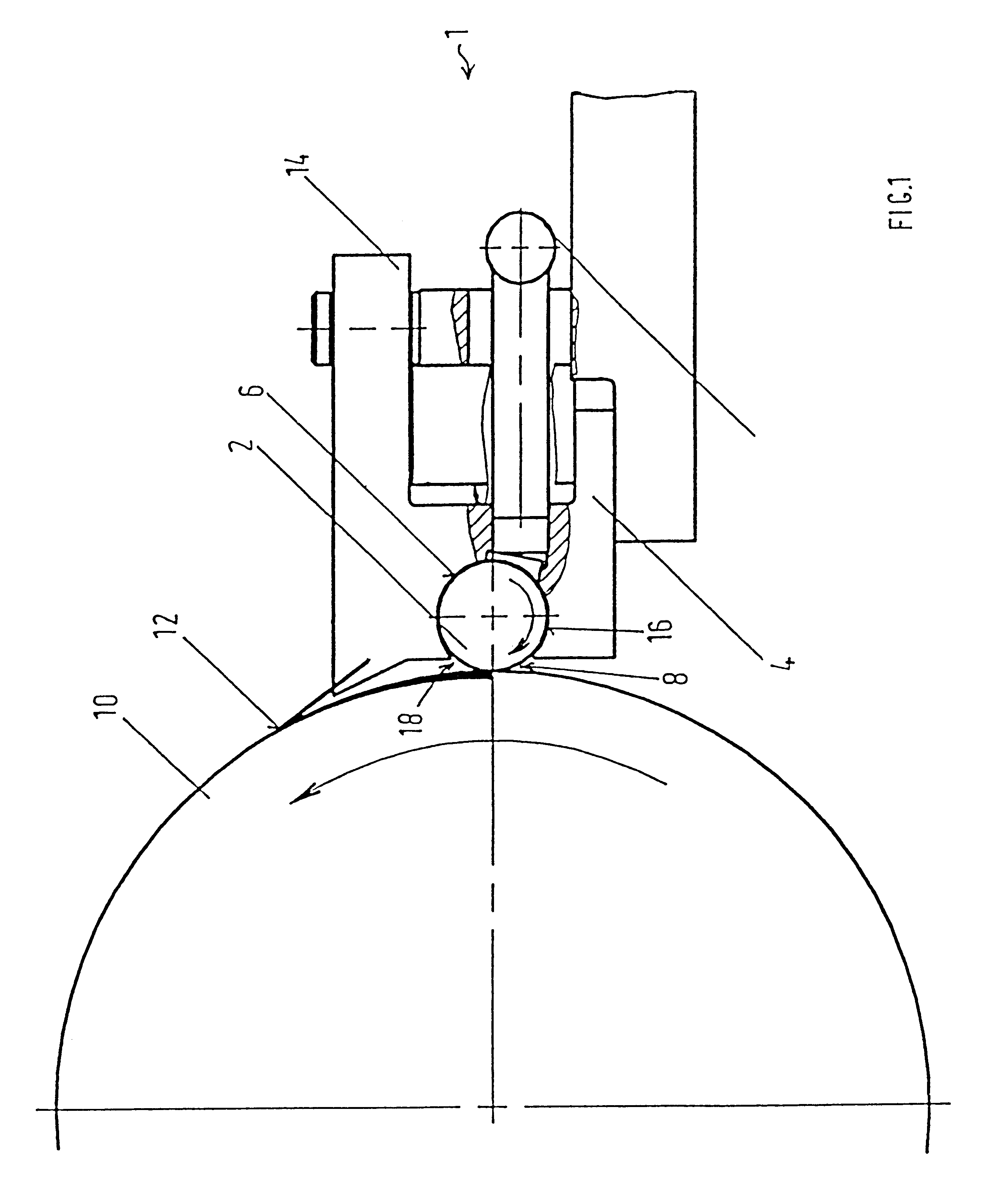
In FIG. 1, a doctor roller apparatus 1 contains a doctor roller 2 which is carried by a doctor roller bed 4 and is pressed with its working surface 6 through a nip 8 onto an ink applicator roller 10 in the inking unit of a printing machine. The ink applicator roller 10, in turn, inks a printing forme, not illustrated for reasons of scale, which is tension-mounted on a forme cylinder. In order to achieve a defined pressing force of the doctor roller 2 on the surface 12 of the ink applicator roller 10, the doctor roller bed 4 is prestressed in the direction of the ink applicator roller 10 by means of one or more diaphragm-type air cylinders 14. The doctor roller 2 is assigned a drive, not illustrated here, by means of which it can be set in rotational movement at an adjustable speed and with an adjustable direction of rotation relative to the ink applicator roller 10.

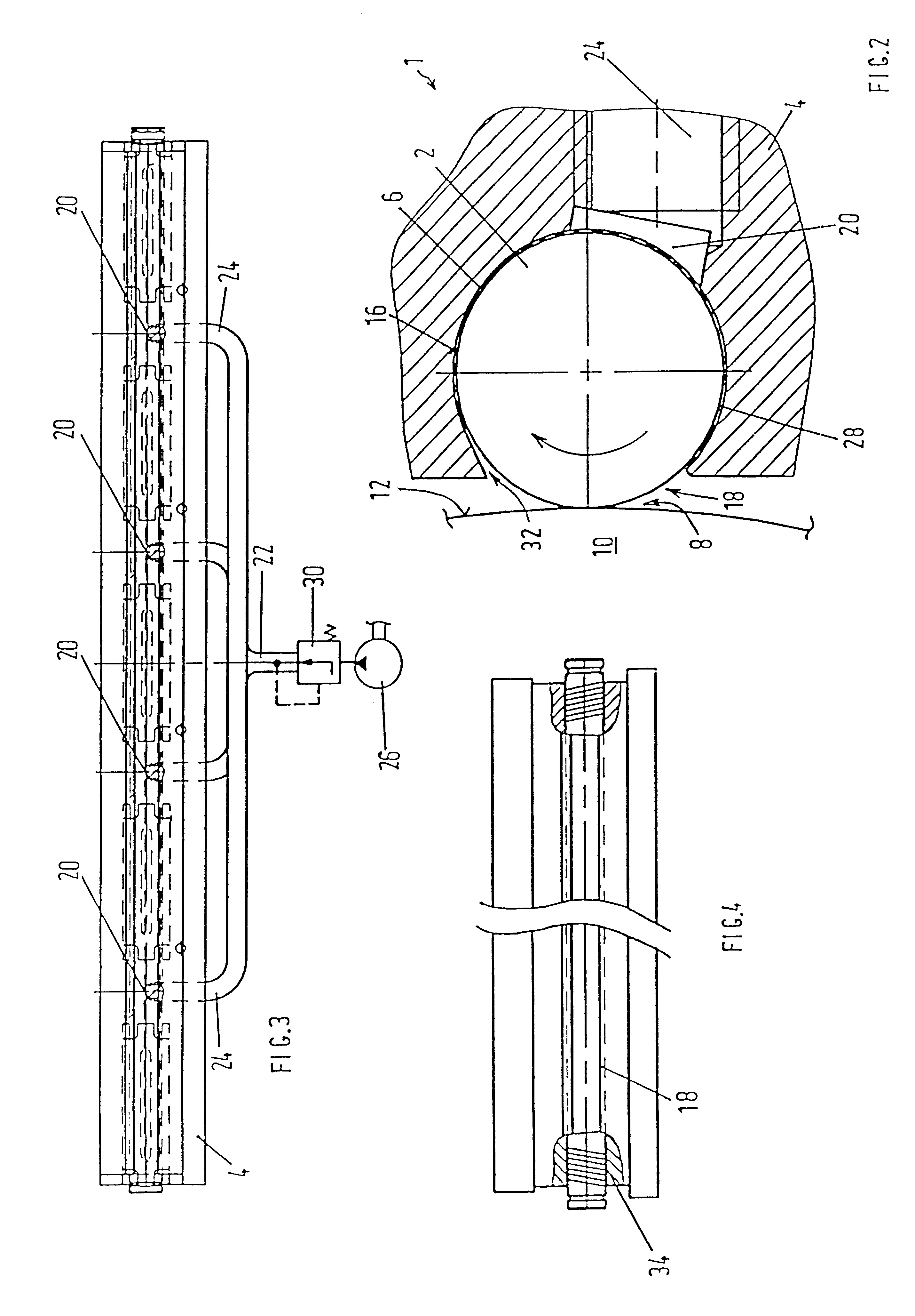
The doctor roller 2 is mounted, on its working surface 6, by means of a cylindrical sliding surface 16 formed in the do...


PUM


Abstract

Apparatus for the metered coating of a printing machine roller with a liquid application medium, in particular for the metered coating of an ink applicator roller with printing ink, containing at least one doctor roller placed with its working surface onto the printing machine roller and carried by a doctor roller bed. The doctor roller is slide-mounted on its working surface by means of at least one sliding surface formed on the doctor roller bed. The application medium can be fed to or discharged from the surface of the printing machine roller by rotation of the doctor roller, through a clearance between the sliding surface and the working surface of the doctor roller. A pressure-regulatable valve for regulating the pressure prevailing in the clearance is arranged between a pressure source for the application medium and the clearance.

Description

1. Field of the InventionThe invention relates to a doctor roller apparatus for the metered coating of a printing machine roller with a liquid application medium, in particular for coating an ink applicator roller with printing ink, of the type having at least one doctor roller supported by a doctor roller bed and placed with its working surface against the printing machine roller.2. Description of the Related ArtSuch a doctor roller apparatus is known from U.S. Pat. No. 5,372,644, in which the ink applicator roller is connected via a nip to a transfer roller, the surface of which dips into a fountain filled with application medium. The fountain is sealed off relative to the transfer roller by means of a barrier doctor blade and a doctor roller. The doctor roller does not cause the fountain to be sealed off completely, since it has an engraving through which a metered quantity of the application medium can flow, this quantity remaining on the surface of the transfer roller. This qua...

Claims


Application Information

Patent Timeline
Patent Type & Authority Patents(United States)
IPC IPC(8): B05C1/08B41F31/02B41F31/20D21H25/12D21H25/00B41F31/12B41F31/08B41F31/14B41F31/15B41F31/26
CPCB05C1/0834B41F31/20B41F31/027D21H25/12
Inventor LESTI, HARALD
Owner MANROLANAD AG
Why Eureka
Try Eureka