Airfoils with improved strength and manufacture and repair thereof

a technology of airfoils and superalloys, which is applied in the field of airfoils with improved strength and manufacture and repair thereof, can solve the problems of high cost of blades made of conventional superalloy materials, unsatisfactory, and difficult to meet the requirements of use, so as to improve the performance of both newly manufactured and repaired airfoils, improve the tensile strength and tensile strength, and improve the effect of tensile strength

Inactive Publication Date: 2003-06-10
GENERAL ELECTRIC CO
View PDF10 Cites 67 Cited by
  • Summary
  • Abstract
  • Description
  • Claims
  • Application Information

AI Technical Summary

Benefits of technology

It would be advantageous if the performance of both newly manufactured and repaired airfoils could be improved to better withstand the aggressive stress-temperature combinations present in localized areas on turbine components. However, it would not be desirable if improvements to creep life and fatigue life were effected at the expense of other design critical requirements of the airfoil. For example, a blade made entirely of DSE material would have excellent creep and fatigue properties, but would cost many times the price of a blade made of conventional superalloy material. Therefore, it would be beneficial if turbine airfoils could be improved in a manner that would allow for enhanced performance in regions susceptible to damage due to locally aggressive conditions without significantly detracting from the overall performance of the airfoil.
One embodiment of the present invention provides a method for repairing a gas turbine airfoil, comprising: a. providing an airfoil having specified nominal dimensions, the airfoil comprising a first material having a creep life and a fatigue life, the airfoil further comprising a leading edge section and a trailing edge section; b. removing at least one portion of at least one section of the airfoil to create at least one deficit of material for the airfoil relative to the specified nominal dimensions, the at least one section selected from the group consisting of the lea...

Problems solved by technology

When one alloy is used to construct the entire airfoil, compromises must be made in the performance of the airfoil because no single alloy possesses ideal values for the long list of properties required for the airfoil application, and because conditions of temperature, stress, impingement of foreign matter, and other factors are not uniform over the entire ai...

Method used


Image

  • Airfoils with improved strength and manufacture and repair thereof
  • Airfoils with improved strength and manufacture and repair thereof
  • Airfoils with improved strength and manufacture and repair thereof

Examples


Embodiment Construction

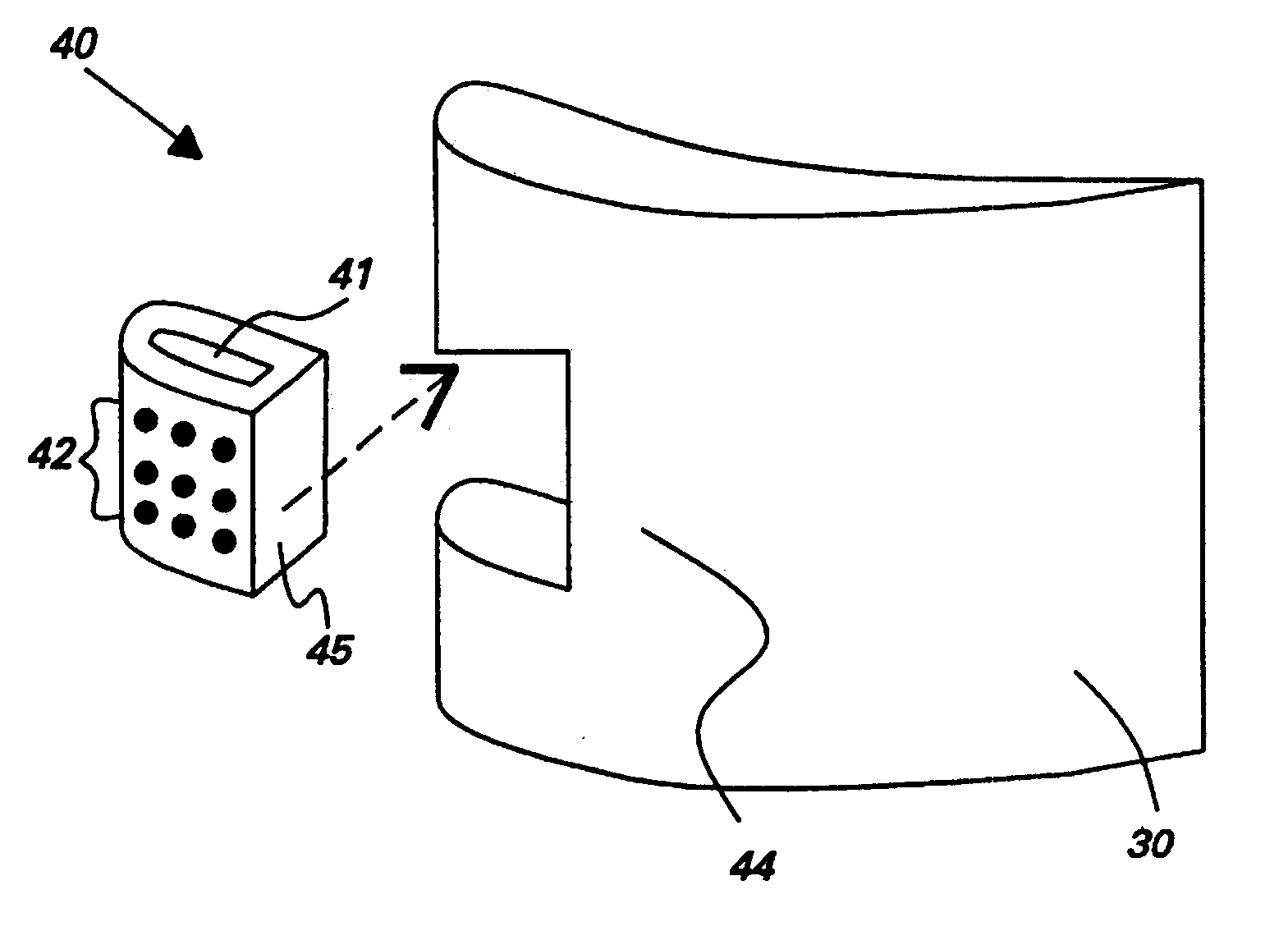
Structure, manufacture, and repair embodiments of the present invention are useful for components that operate at elevated temperatures, and particularly components of gas turbine engines such as the airfoils of blades (also referred to as "buckets") and vanes (also referred to as "nozzles") where the maximum metal temperatures typically range from about 1000.degree. C. to over about 1200.degree. C. in current systems and temperatures over about 1300.degree. C. are envisioned for future applications.

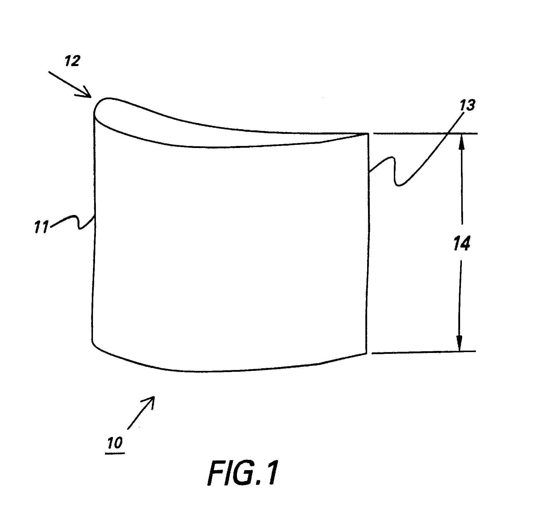
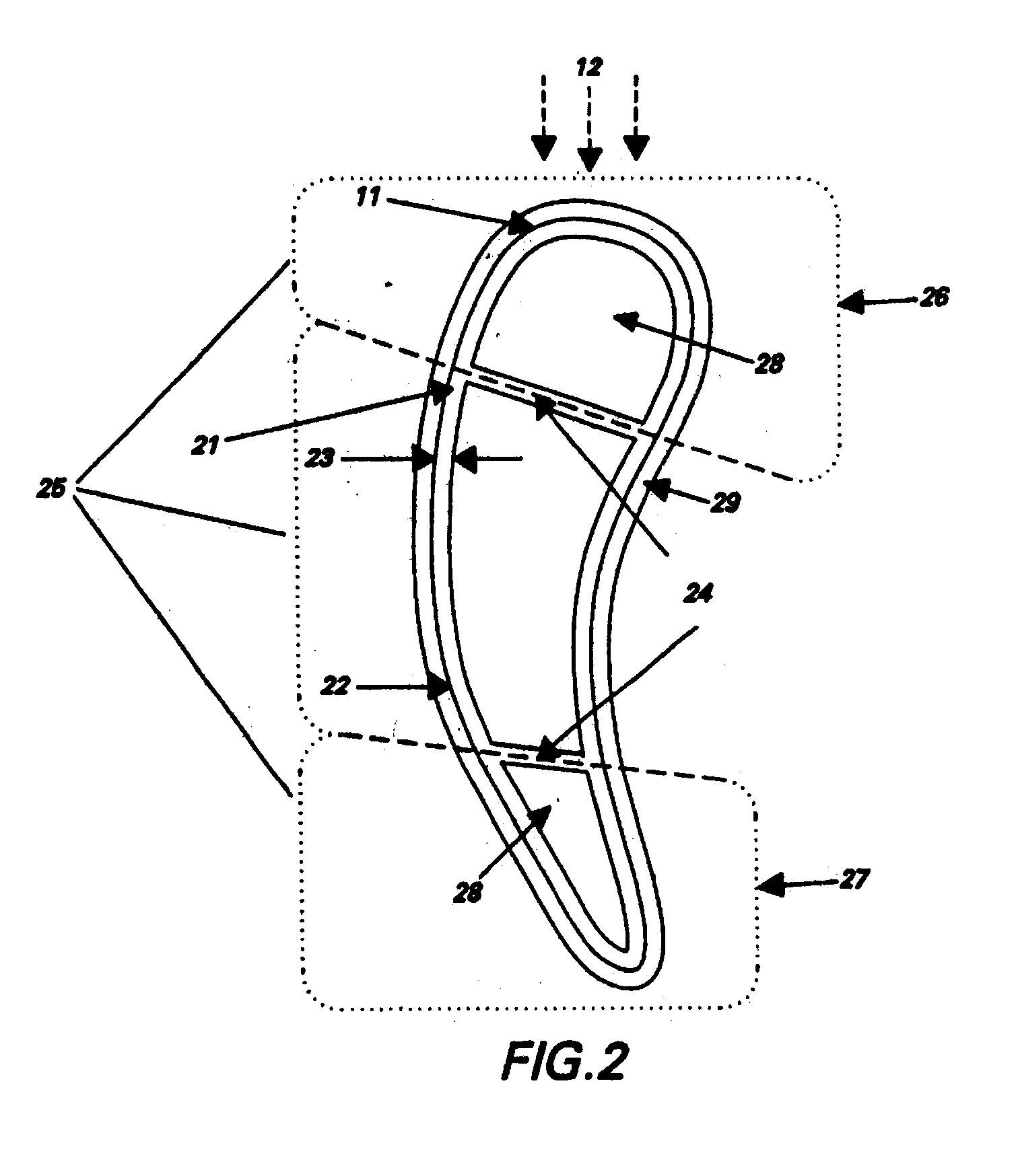
Referring to FIG. 1, a gas turbine airfoil 10 comprises a leading edge 11 located at the edge of the airfoil which, during operation, is first contacted by the flow of gas 12; and a trailing edge 13 located at the edge of the airfoil on the opposite side of the airfoil from the leading edge 11. The cross-sectional view of the airfoil in FIG. 2 shows that the airfoil further comprises an external wall 21 with an external surface 22 that defines the perimeter of the airfoil, and the extern...


PUM

PropertyMeasurementUnit
Fractionaaaaaaaaaa
Timeaaaaaaaaaa
Thicknessaaaaaaaaaa

Abstract

Methods for repairing and manufacturing a gas turbine airfoil, and the airfoil repaired and manufactured with such methods are presented with, for example, the repair method comprising providing an airfoil having specified nominal dimensions, the airfoil comprising a first material, the first material having a creep life and a fatigue life, the airfoil further comprising a leading edge section and a trailing edge section; removing at least one portion of at least one section of the airfoil to create at least one deficit of material for the airfoil relative to the specified nominal dimensions, the at least one section selected from the group consisting of the leading edge section and the trailing edge section; providing at least one insert comprising a second material, the second material having a creep life that is at least substantially equal to the creep life of the first material, and a fatigue life that is at least substantially equal to the fatigue life of the first material; and disposing the at least one insert onto the airfoil such that the at least one deficit of material is substantially eliminated.

Description

BACKGROUND OF INVENTIONThe present invention relates to components designed to operate at high temperatures. More particularly, this invention relates to methods for repair and manufacture of airfoils for gas turbine engines, and the articles made and repaired from the use of these methods.In a gas turbine engine, compressed air is mixed with fuel in a combustor and ignited, generating a flow of hot combustion gases through one or more turbine stages that extract energy from the gas, producing output power. Each turbine stage includes a stator nozzle having vanes which direct the combustion gases against a corresponding row of turbine blades extending radially outwardly from a supporting rotor disk. The vanes and blades include airfoils having a generally concave "pressure" side and a generally convex "suction" side, both sides extending axially between leading and trailing edges over which the combustion gases flow during operation. The vanes and blades are subject to substantial h...

Claims


Application Information

Patent Timeline
IPC IPC(8): B23P6/00B23P15/04F01D5/00F01D5/28
CPCB23P6/005F01D5/005F01D5/28B23P15/04Y10T29/49318F05C2201/0463F05C2201/0466Y02T50/67Y02T50/672F05D2230/21F05D2230/23F05D2230/80F05D2300/11F05D2300/606F05D2300/607F05D2300/502Y10T29/49737Y02T50/60
Inventor JACKSON, MELVIN ROBERTFROST, AARON TODDHUANG, SHYH-CHINMUKIRA, CHARLES GITAHRABER, THOMAS ROBERTWHITE, RAYMOND ALANDUPREE, PAUL LEONARDHARDWICKE, CANAN USLU
Owner GENERAL ELECTRIC CO
Why Eureka
Try Eureka