Pressure control system using input current sensing

a control system and input current technology, applied in the direction of machines/engines, mechanical equipment, positive displacement liquid engines, etc., can solve the problems of limiting the useful life of equipment, brushless dc motors, and sparking of commutators, etc., and have not been widely known in these applications

Inactive Publication Date: 2003-06-10
MOOG INC
View PDF2 Cites 54 Cited by
  • Summary
  • Abstract
  • Description
  • Claims
  • Application Information

AI Technical Summary

Problems solved by technology

While inexpensive, these motors have certain drawbacks.
Among these are brush wear which can limit the useful life of the equipment, and sparking of the commutator, which may be a hazard

Method used


Image

  • Pressure control system using input current sensing
  • Pressure control system using input current sensing
  • Pressure control system using input current sensing

Examples


Embodiment Construction

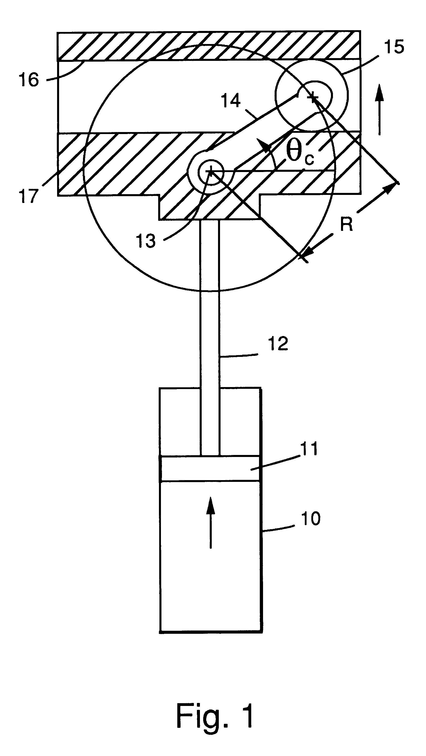
FIG. 1 illustrates a crank mechanism for coupling a brushless DC motor (not shown) to a piston rod 12. The piston rod 12 connects to a piston 11 inside a cylinder 10. The motor output shaft connects through a gear reduction mechanism (not shown in FIG. 1) and an output drive shaft 13 which connects to one end of a crank arm 14 and provides a stationary axis around which the crank arm 14 rotates. The other end of the crank arm 14 is connected to a roller 15. The roller 15 moves in a slot 16 in coupling block member 17 which is fastened to one end of the piston rod 12. As the drive shaft 13 rotates, it causes pivoting of the crank arm 14 around the stationary axis provided by drive shaft 13. As the crank arm 14 rotates 360.degree. around stationary axis 13, the coupling member 17 moves up and down to draw the piston 12 in one direction and then drive it in the opposite direction into the cylinder 12 in a reciprocating motion.

In a reciprocating pump, the relationship between crankshaft...


PUM


Abstract

A method and apparatus for controlling the output function of a permanent magnet brushless DC motor (20), by sensing an input current to the motor (20), by computing an output torque generated by the motor (20) as a function of the input current to the motor (20), by computing an output pressure for a pump (22) in response to the output torque, by reading a set point pressure, and by comparing the set point pressure to the output pressure, and in response thereto controlling on-off operation of the motor (20). The apparatus includes a sensing circuit (28) and a microelectronic processor (30) for performing these functions.

Description

This invention relates to a system for controlling a motor driven function by sensing the input current to the motor, and more particularly controlling the pressure of a pump by sensing the input current to a permanent magnet (PM) brushless motor.DESCRIPTION OF THE PRIOR ARTPresently, many fluid pumps, including air compressors, use series wound (universal) brush motors that are powered directly from an AC power line. While inexpensive, these motors have certain drawbacks. Among these are brush wear which can limit the useful life of the equipment, and sparking of the commutator, which may be a hazard in certain environments. The pressure in these pump systems is controlled by energizing a motor when the pressure drops below a set point threshold and de-energizing the motor when it rises above the set point threshold. A pressure sensor, either a mechanical type that directly operates a motor energizing switch or a strain gauge type that electronically controls such a switch, regulat...

Claims


Application Information

Patent Timeline
IPC IPC(8): F04B49/06
CPCF04B49/065F04B2203/0201F04B2203/0207Y10S388/93F04B2207/042Y10S388/929F04B2205/05
Inventor PIEDL, MARTINBARANI, MOE K.FLANARY, RON
Owner MOOG INC
Why Eureka
Try Eureka