
Wideband variable gain amplifier with low power supply voltage

a variable gain amplifier and power supply voltage technology, applied in differential amplifiers, amplifiers with semiconductor devices/discharge tubes, amplification control details, etc., can solve the problems of limiting the operational bandwidth, power consumption producing a practical need, and variable gain amplifiers exhibiting this higher rail-to-rail voltag

Inactive Publication Date: 2003-06-24
EUVIS
View PDF1 Cites 15 Cited by
  • Summary
  • Abstract
  • Description
  • Claims
  • Application Information

AI Technical Summary

Problems solved by technology

Variable gain amplifiers exhibiting this higher rail-to-rail voltage inherently consume more power than the similarly sized fixed-gain amplifiers.
Not surprisingly, the power consumption produces a practical need for an extra or enhanced power supply beyond that nominally required for conventional fixed-gain amplifiers.
This compensation circuitry can introduce additional parasitic effects that result in limiting the operational bandwidth.
This mediocre isolation can cause serious stability problems when the variable amplifier is used in an automatic-gain-control (AGC) loop.

Method used


Image

  • Wideband variable gain amplifier with low power supply voltage
  • Wideband variable gain amplifier with low power supply voltage
  • Wideband variable gain amplifier with low power supply voltage

Examples


Embodiment Construction

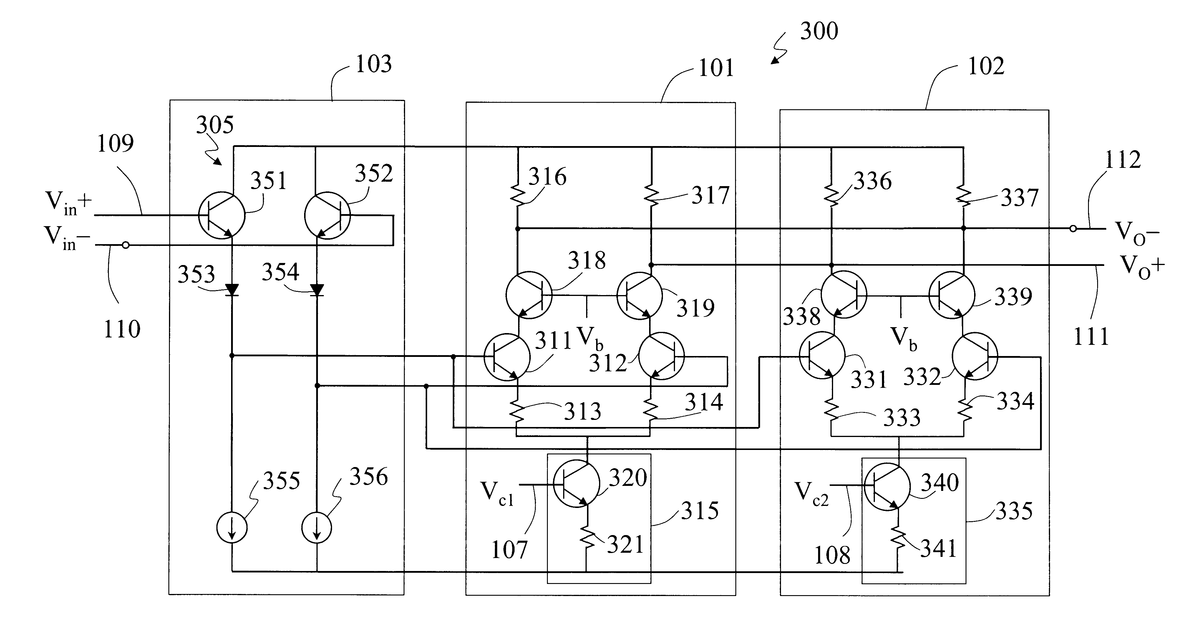
FIG. 5 illustrates an alternative embodiment of the present invention. The first gain module 101 is comprised of common-emitter transistors 411 and 412, a current generator 415 and a pair of emitter degeneration resistors 413 and 414. Similarly, the second gain module 102 is comprised of common-emitter transistors 431 and 432, a current generator 435, and emitter degeneration resistors 433 and 434. The bias currents I.sub.B1 105 and I.sub.B2 106 of the gain modules 101 and 102 are provided by transistors 420 and 440 with emitter resistors 421 and 441, respectively. The combining module is comprised of a pair of common-base transistors 441 and 442 with resistive loads 443 and 444.

Each bias current of the gain modules 101 and 102 can be adjusted independently according to the present variable gain amplifier invention. Since the overall gain of the invented variable gain amplifier is determined by the difference of controlled bias current I.sub.B1 and I.sub.B2, it is possible to achiev...


PUM


Abstract

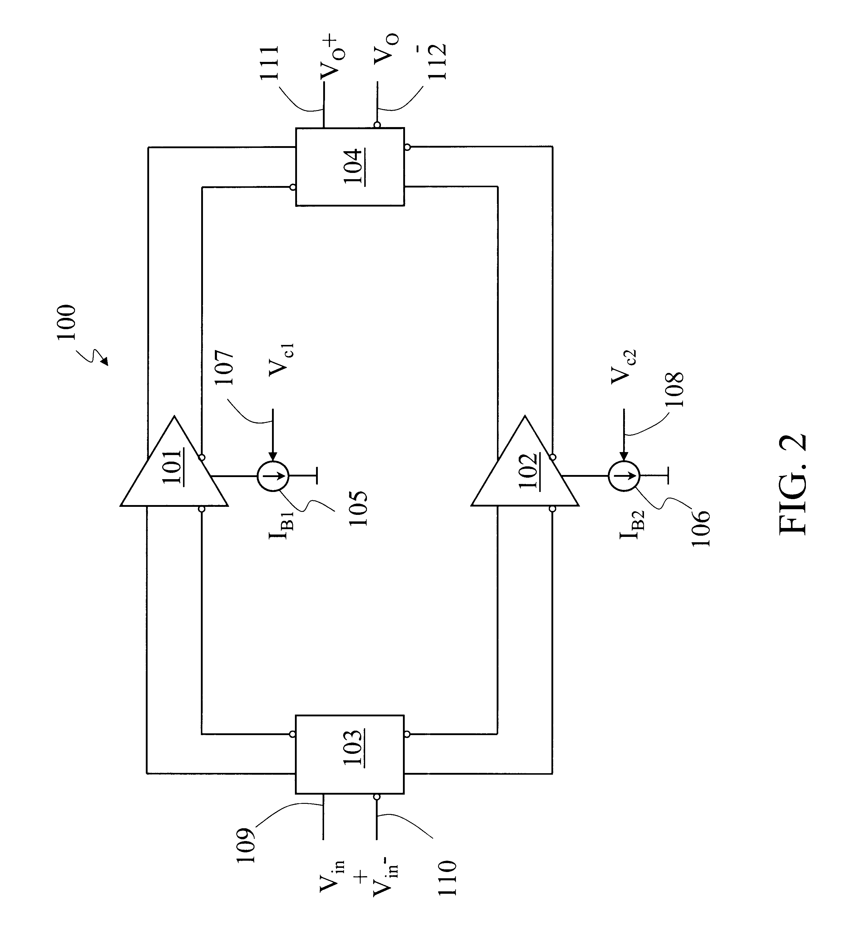
A circuit for a variable gain amplifier is disclosed that uses two differential gain stages with independently adjustable bias currents. By changing the bias currents of the gain stages, the overall gain and phase of the amplifier can be adjusted over a wide range. Neither in-series nor in-parallel circuitry is required to implement or perform gain control. In addition to minimal part requirements for mechanization, the present invention features low power supply requirements while maintaining a wide operational bandwidth.

Description

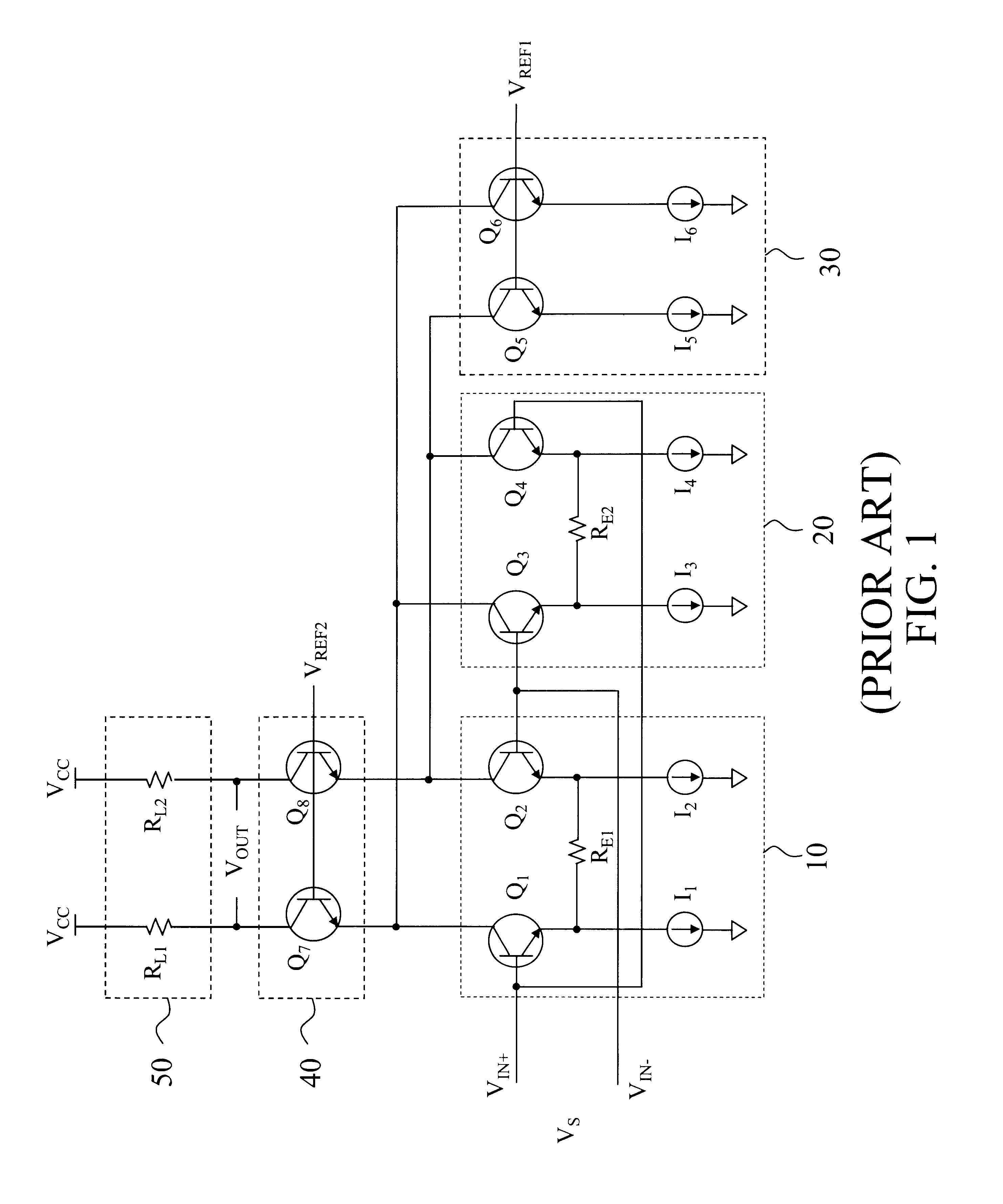
BACKGROUND--FIELD OF THE INVENTIONThe present invention relates to transistorized variable gain amplifiers particularly suited for adjustable gain control and automatic gain control.BACKGROUND--Description of Prior ArtTypically, amplifiers achieve variable gain control by coupling a pair of gain stages where their outputs are connected oppositely and both gain stages share the same bias current. The bias current of both gain stages are then differentially controlled by a pair of in-series transistors. This topology is termed a Gilbert cell. Amplifiers exploiting a Gilbert cell can provide wide variations in gain. However, because of in-series control circuitry, the minimal rail-to-rail voltage is higher for the typical variable gain amplifier when compared to a conventional fixed-gain amplifier. Variable gain amplifiers exhibiting this higher rail-to-rail voltage inherently consume more power than the similarly sized fixed-gain amplifiers. Not surprisingly, the power consumption pro...

Claims


Application Information

Patent Timeline
IPC IPC(8): H03F3/45H03G1/00H03F3/68
CPCH03F3/45089H03F3/68H03G1/0023H03F2203/45578H03F2203/45612H03F2203/45466
Inventor LIU, CHEH-MING JEFFCHANG, KAI-CHUN
Owner EUVIS
Learn More