Torsional vibration damper

a torsional vibration and damper technology, applied in the direction of fluid couplings, ring springs, gearing, etc., can solve the problems of large structural space, disadvantageous damping performance, and significantly longer spring travel

Inactive Publication Date: 2003-07-01
ZF FRIEDRICHSHAFEN AG
View PDF16 Cites 26 Cited by
  • Summary
  • Abstract
  • Description
  • Claims
  • Application Information

AI Technical Summary

Benefits of technology

In the torsional vibration damper according to the invention, then, the principle of compressible helical springs or the like is relinquished; instead, deformation regions extending from radially outward to radially inward and capable of deformation are used and introduce the necessary elasticity into the torque transmission path. As, moreover, at least two damper members having such deformation regions are used in the torsional vibration damper according to the invention it is possible, for example, by producing the damper members by stamping technology from sheet metal material, by appropriate selection of the number of damper members or of the material thereof to combine a desired damping performance with ease of manufacture.
Alternatively, it is possible to provide that, for at least one of the damper members, the radially outward coupling region and / or the radially inward coupling region is or are coupled or capable of being coupled to, respectively, a radially outward coupling region and a radially inward coupling region of at least one further damper member. This ultimately means that at least two damper members are connected in series relative to one another, which results in a significantly longer spring travel.

Problems solved by technology

Such arrangements require a relatively large amount of structural space and, in addition, are subject to the problem that the helical springs, extending approximately in the circumferential direction, are displaced radially outward by centrifugal force in rotating operation and, in doing so, make frictional engagement with at least one of the components.
This frequently results, at least at relatively high speeds of rotation, in a disadvantageous effect on damping performance.
This ultimately means that at least two damper members are connected in series relative to one another, which results in a significantly longer spring travel.

Method used


Image

  • Torsional vibration damper
  • Torsional vibration damper
  • Torsional vibration damper

Examples


Embodiment Construction

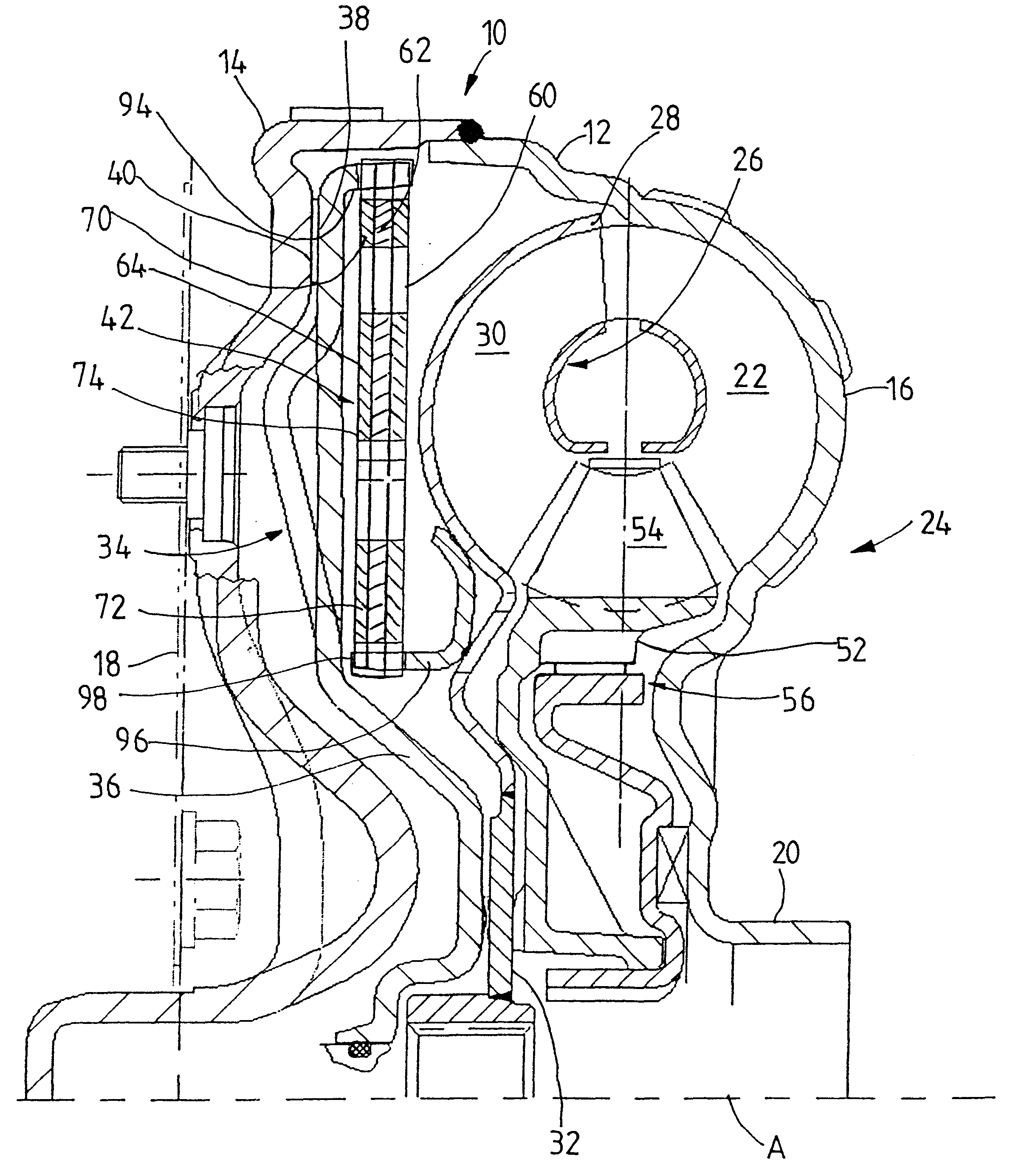
In FIG. 1, a hydrodynamic torque converter 10 includes a housing arrangement 12, which in turn comprises a housing lid 14 and a pump impeller shell 16 connected thereto in the radially outward region by welding or the like. The housing lid 14 is connected or can be connected via a coupling arrangement 18 to a drive shaft (not shown), in a manner fixed in rotation, and the pump impeller shell 16 is formed in its radially inward region integrally with a pump impeller hub 20. Furthermore, the pump impeller shell 16 carries a plurality of pump impeller blades 22 in its radially outward region, the pump impeller shell 16 with the pump impeller hub 20 integrally formed thereon and the pump impeller blades 22 ultimately forming a pump impeller 24. A turbine wheel 26 is also provided in the interior space of the torque converter 10. This turbine wheel comprises a turbine wheel shell 28, which bears a plurality of turbine wheel blades 30 in its radially outward region and is fixedly connecte...


PUM


Abstract

A torsional vibration damper for incorporation into the torque transmission path between two components or subassemblies, especially for a hydrodynamic coupling device, includes at least two disk-like damper members. Each damper member has a radially outward coupling region and a radially inward coupling region, and at least one deformation region extending between the radially outward coupling region and the radially inward coupling region. Each deformation region is elastically deformable at least in some areas to permit a relative circumferential movement between the radially outward coupling region and the radially inward coupling region.

Description

1. Field of the InventionThe present invention relates to a torsional vibration damper for incorporation into the torque transmission path between two components or subassemblies, especially for a hydrodynamic coupling device.2. Description of the Related ArtSuch torsional vibration dampers are used, for example, in the torque transmission path between a clutch piston of a lockup clutch arrangement and a turbine wheel, but may also be used in clutch plates or multiple-mass flywheels. Helical springs are generally provided as the damper members to provide the necessary elasticity and can be subjected to the action of respective control regions or control edges of two components or subassemblies that can be twisted relative to one another about an axis of rotation. When torsional vibrations occur as a result of the interaction with the respective control edges, the helical compression springs, whose longitudinal axes extend approximately in the circumferential direction, can be compre...

Claims


Application Information

Patent Timeline
Patent Type & Authority Patents(United States)
IPC IPC(8): F16F15/121F16F1/02F16F1/34F16H45/02F16H45/00
CPCF16F1/34F16F15/1213F16H45/02F16H2045/0247F16H2045/0294F16F1/10
Inventor REINHART, EDGARBECHMANN, DIETRICHMEYER, ANDRESCHRAMM, FRIEDRICHSASSE, CHRISTOPHWACK, ERWINSUDAU, JORG
Owner ZF FRIEDRICHSHAFEN AG
Why Eureka
Try Eureka