
Sterilization system

a sterilization system and sterilization method technology, applied in the direction of material analysis using wave/particle radiation, chemical methods analysis, instruments, etc., can solve the problems of no conditions defined to achieve sterility, time-consuming and laborious sterilization step of batch-wise autoclave, and inapplicability of ultraviolet calorimeter to calibrate a photodetector to international standards

Inactive Publication Date: 2003-07-15
JOHNSON & JOHNSON VISION CARE INC
View PDF74 Cites 113 Cited by
  • Summary
  • Abstract
  • Description
  • Claims
  • Application Information

AI Technical Summary

Benefits of technology

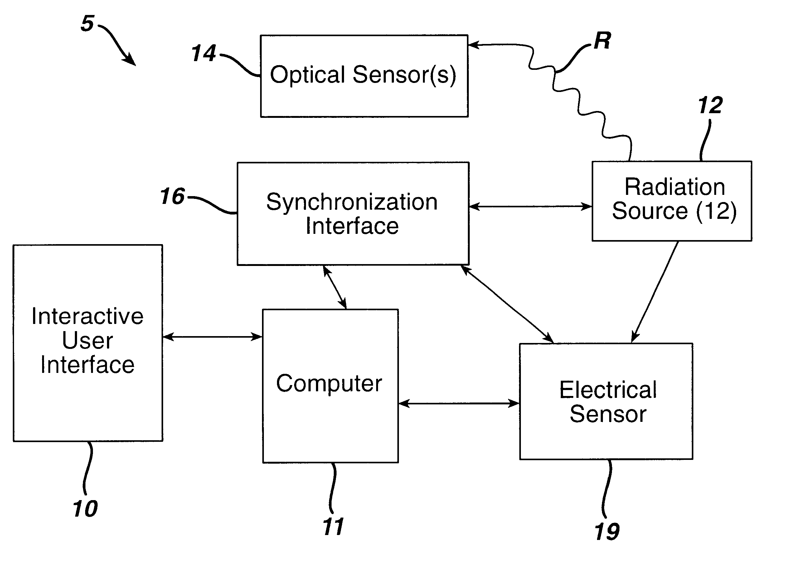
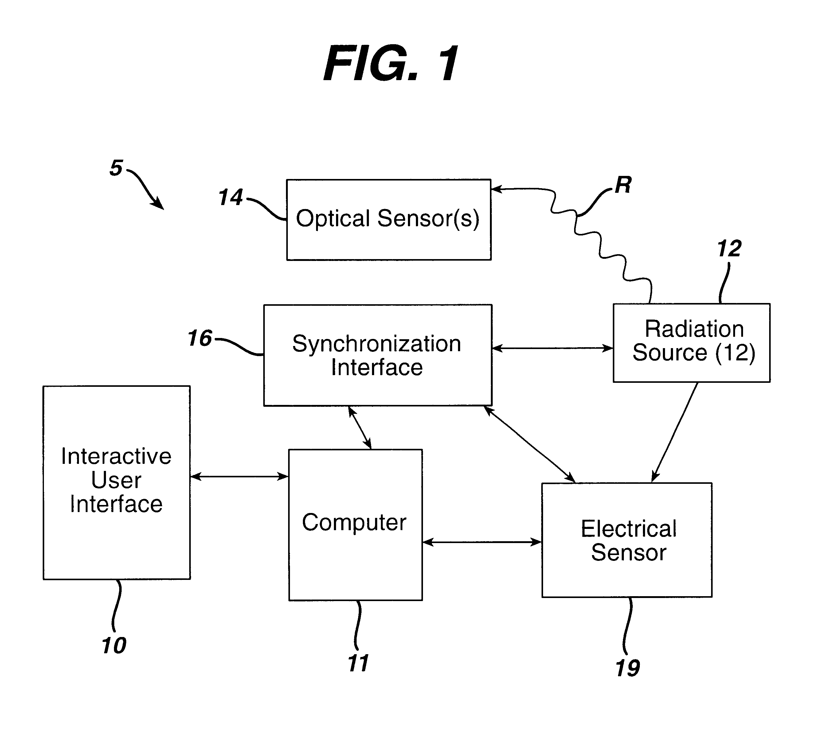
The sterilization system and method of this invention comprise a radiation source to sterilize products, preferably medical devices. The sterilization system and method can be used to measure the radiation to which the product is exposed. The system and method described herein are well-suited for in-line manufacturing, and will provide accurate measurements of the radiation to which a product is exposed to assure that every product receives a sterilizing dose of radiation.

Problems solved by technology

Although this commercial process produces thoroughly sterilized contact lenses, the batch-wise autoclave sterilization step is time consuming, costly, and inefficient.
U.S Pat. No. 5,786,598 discloses the idea of using a flash lamp system to sterilize contact lenses in a preserved solution in a container, however, there are no conditions defined to accomplish sterility, nor examples which show that sterility can be accomplished.
Further, it is not appropriate to use an ultraviolet calorimeter to calibrate a photodetector to international standards.
An ultraviolet calorimeter only provides a single measurement of the total energy in the ultraviolet range, and does not provide any spectral information.
If the ultraviolet calorimeter were used to provide instantaneous and in-line monitoring, the process of sterilizing using pulsed light sterilization would be either ineffective or so slow, it would not be desirable.

Method used


Image

  • Sterilization system
  • Sterilization system
  • Sterilization system

Examples


example 1

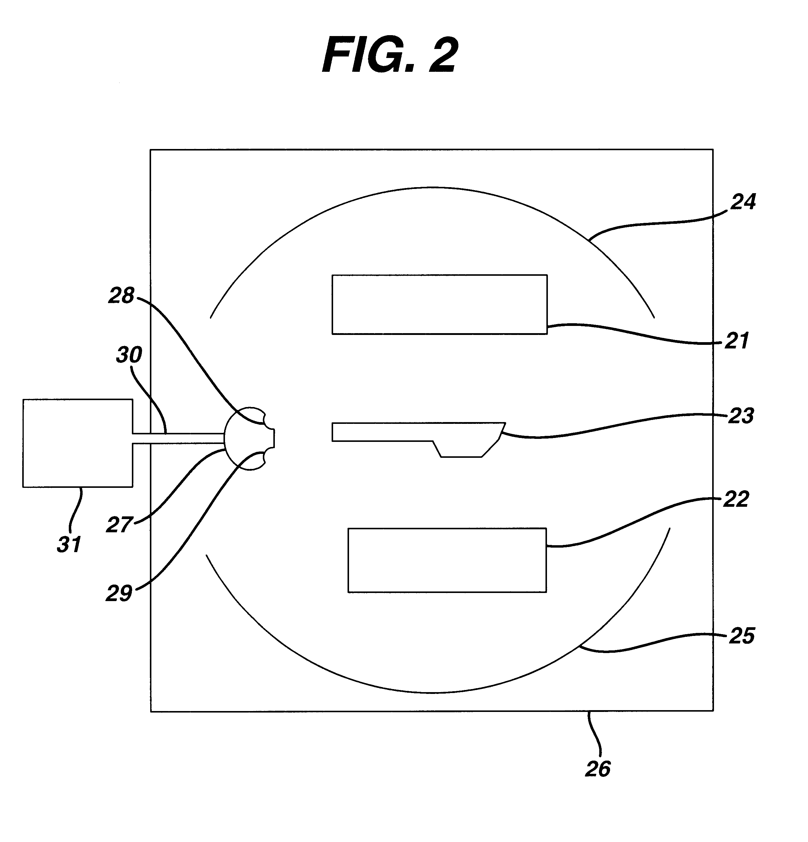
The control system described herein was used to generate a spectroradiometric map of a single radiation source for a PurePulse PB1-4 system. The radiation between from 240 to 280 nm was measured at 21 mm from one of two lamps, at a power level of 52%. The radiation was measured in 5 mm increments -25 mm to 25 mm from the center of lamp perpendicular to the axis of the lamp. The graph produced by the system is shown in FIG. 3.

example 2

Spectroradiometric measurements of a lamp were made when the lamp was new and after 2600 flashes of the lamp. Although the total energy of the lamp had only decreased by 3.4% (as measured with a thermopile calorimeter), FIG. 4 shows that the energy of the lamp between 240 and 280 nm (the range of radiation critical for sterilization) had decreased by 8.6%. The change in the energy of the lamp between 240 and 280 nm, was enough to result in the survival of the more resistant microorganisms; however, this change would not be detected by a system which only measures the change in the overall energy. In FIG. 4, the spectroradiometric measurements of the new lamp are the solid line, and the spectroradiometric measurements of the lamp after 2600 flashes is the dashed line.


PUM


Abstract

A sterilization system comprising: radiation source; optical and / or electrical sensors; and timing means; wherein the measurement of radiation by the optical sensor is substantially synchronized based on the timing means to the start and end of each pulse of radiation from the radiation source or to the start and end of the exposure of a product to the radiation source.

Description

This invention relates broadly to sterilization of medical devices by ultraviolet radiation. More specifically, this invention relates to a sterilization system by which the amount of radiation produced by the sterilization system is measured, and to the method of measuring and controlling the amount of radiation produced by the sterilization system.DESCRIPTION OF THE RELATED ARTMedical device sterilization processes and in particular commercial contact lens manufacturing sterilization processes typically involve some form of temperature and / or pressure-based sterilization techniques. For example, a hydrophilic contact lens is typically first formed by injecting a monomer mixture into a mold. The monomer mixture is then polymerized (i.e. the lenses are cured). After other optional processing steps, such as quality inspections, the lens is placed in a container with a solution and the container is sealed. The packaged lens is sterilized by placing the container in an autoclave at an ...

Claims


Application Information

Patent Timeline
IPC IPC(8): A61L12/00A61L12/06A61L2/10B65B25/00A61L2/08A61L2/00B65B55/08
CPCA61L2/10A61L12/063B65B25/008A61L2/00
Inventor EBEL, JAMES A.ENNS, JOHN B.DEHKORDI, PEYMANINGRAM, DOUGLASKIMBLE, ALLAN W.
Owner JOHNSON & JOHNSON VISION CARE INC
Learn More