Magnetostrictive device for torque sensor and method of manufacture of the same
a torque sensor and magnetostrictive technology, which is applied in the manufacture/assembly of magnetostrictive devices, measurement devices, instruments, etc., can solve the problems of difficult control of the shape formed by the shot peening, and difficulty in increasing the flat area at the cres
- Summary
- Abstract
- Description
- Claims
- Application Information
AI Technical Summary
Problems solved by technology
Method used
Image

Examples
embodiment 1
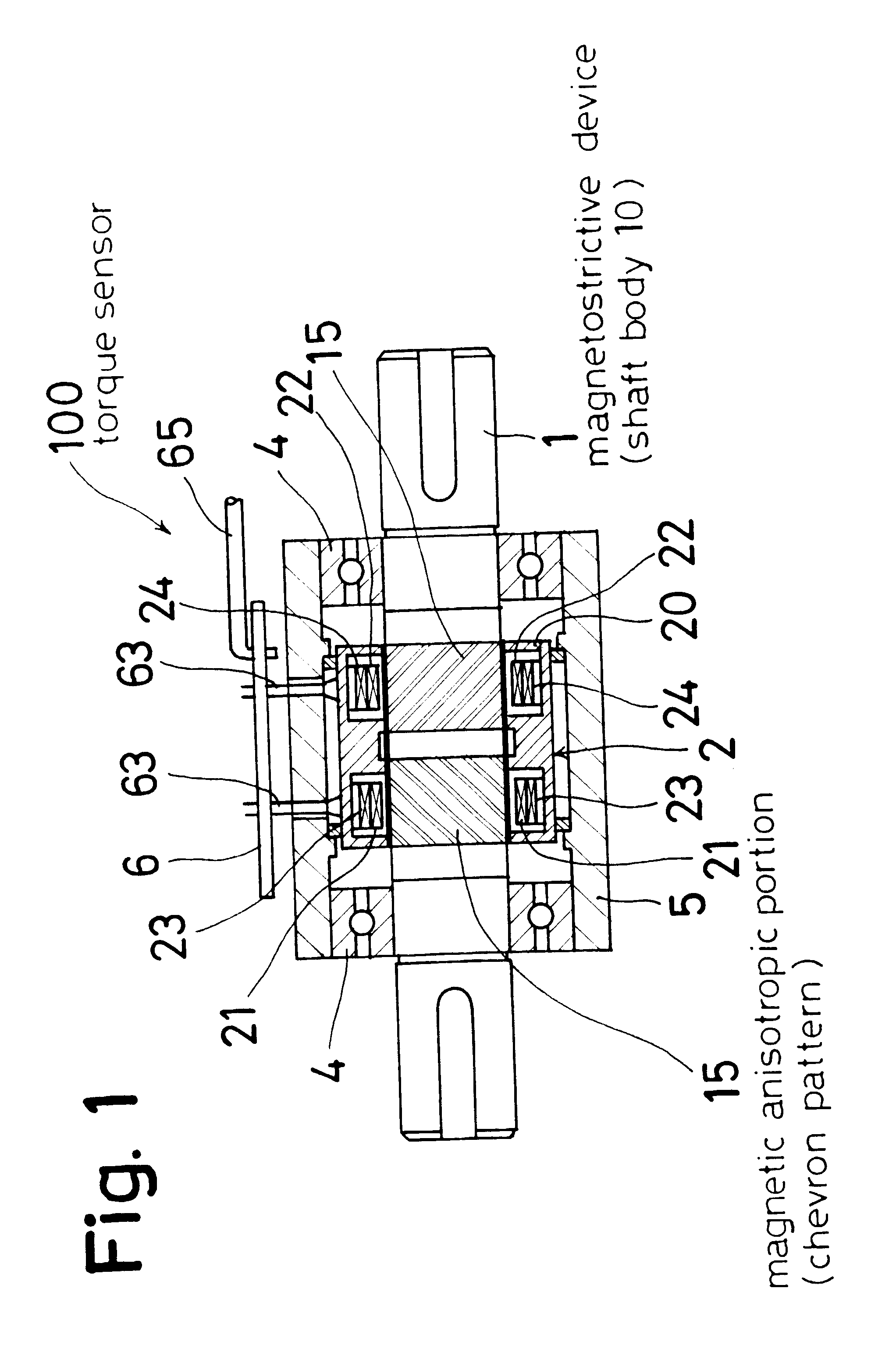
A magnetostrictive device for a torque sensor and a method of its manufacture according to this embodiment of the invention will be described by referring to FIGS. 1 to 6.
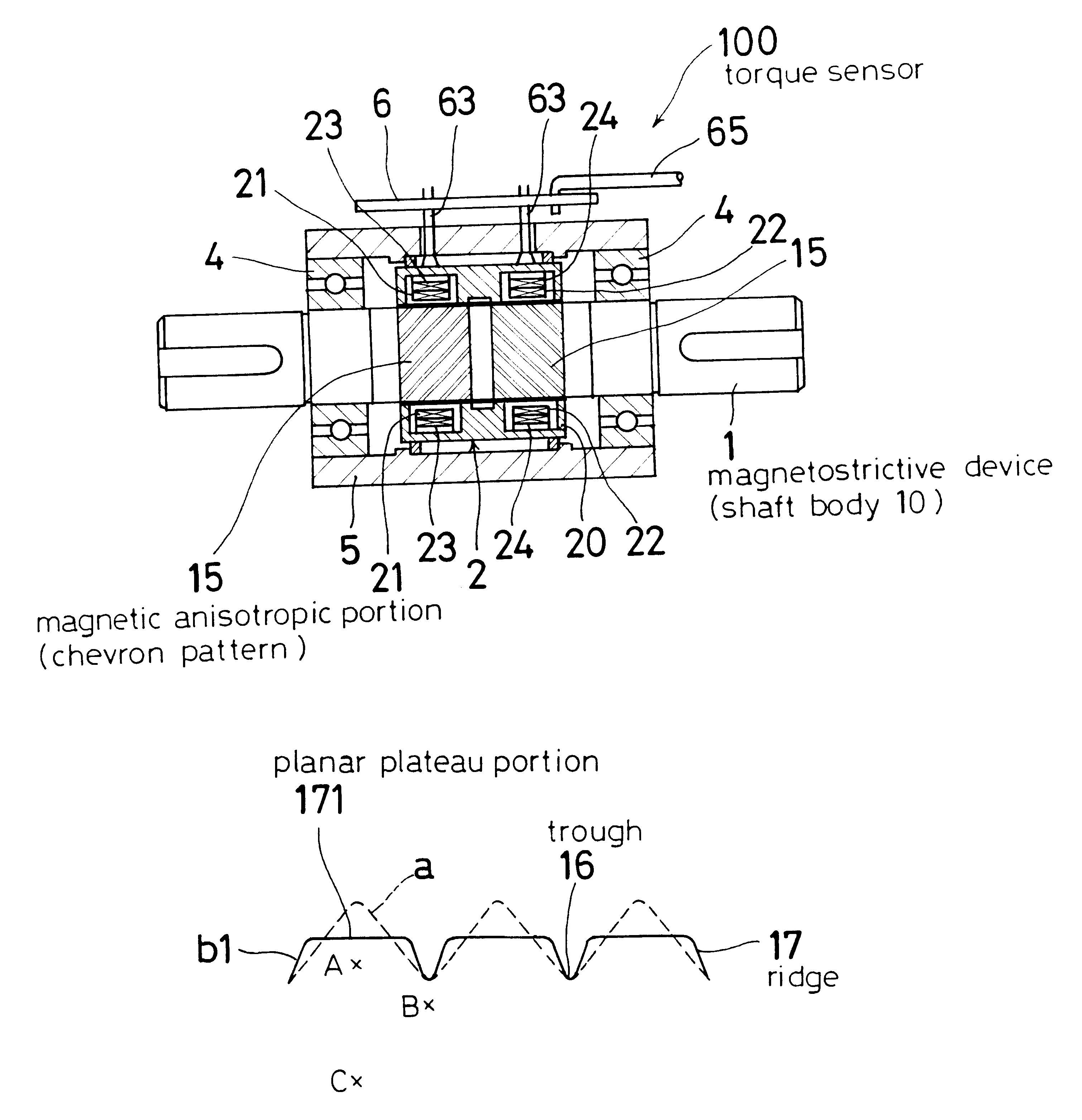
The magnetostrictive device for torque sensor 1 of this embodiment, as shown in FIG. 1, is the one used for a magnetostrictive torque sensor 100.
In this example, three kinds of magnetostrictive devices 1 using a Fe--Cr alloy material are prepared: two kinds (E1, E2) as the specimens of this invention and one kind (C1) as a specimen for comparison. Their performances are compared.
These magnetostrictive devices are adjusted to have a hardness of about Hv300 in the shaft body for ease of comparison.
The magnetostrictive devices of this embodiment (E1, E2, C1) all have a measuring torque range of +7 to -7 Nm.
(Procut of the Invention E1)
The specimen of the invention E1, as shown in FIG. 1, is a magnetostrictive device for a torque sensor having a magnetic anisotropic portion 15 formed on the surface of a shaft body 10.
Th...
embodiment 2
In this example, a Fe--Cr alloy material similar to the one used in the Embodiment 1 was used to manufacture magnetostrictive devices, which were adjusted to have the hardness inside the shaft body of about Hv350 or higher, and their performances were evaluated. The magnetostrictive devices prepared are one kind of specimen of the invention (E3) and two kinds of specimens for comparison (C2, C3).
(Specimen of the Invention E3)
The specimen of the invention E3 was fabricated in a manner similar to the specimen of the invention E2 in the Embodiment 1, except that only the tempering temperature was changed to 600.degree. C. The excess load torque was applied one time as in the case of the specimen of the invention E1.
(Specimen for Comparison C2)
The specimen for comparison C2 was manufactured in a manner similar to the comparison specimen C1 of the Embodiment 1, except that only the tempering temperature was changed to 600.degree. C. The excess load torque was applied one time as in the c...
embodiment 3
In this embodiment, the specimen of the invention E3 and comparison specimen C2 of the Embodiment 2 are used to evaluate the stability against excess load torques.
In more detail, the magnetostrictive devices were used to form the torque sensors 100 as described above and an excess load torque of 100 Nm was applied for three excitation frequencies, 20 kHz, 30 kHz and 50 kHz, to measure the zero point drift (%). The method of measuring the zero point drift is the same as described above.
The result of measurement is shown in Table 3.
As shown in Table 3, the specimen of the invention E3 has a smaller zero point drift than the comparison specimen C2 for all frequencies, indicating that the specimen E3 is excellent in the stability against excess load torque.
It is also found that the lower the frequency, the greater the degree to which the specimen E3 is superior in improving the stability against excess load torque to the comparison specimen C2. This is considered due to the fact that th...
PUM
| Property | Measurement | Unit |
|---|---|---|
| Electrical inductance | aaaaa | aaaaa |
| Temperature | aaaaa | aaaaa |
| Temperature | aaaaa | aaaaa |
Abstract
Description
Claims
Application Information
 - R&D
- Intellectual Property
- Life Sciences
- Materials
- Tech Scout
- Unparalleled Data Quality
- Higher Quality Content
- 60% Fewer Hallucinations
Browse by: Latest US Patents, China's latest patents, Technical Efficacy Thesaurus, Application Domain, Technology Topic, Popular Technical Reports.
© 2025 PatSnap. All rights reserved.Legal|Privacy policy|Modern Slavery Act Transparency Statement|Sitemap|About US| Contact US: help@patsnap.com