Magnetic random access memory array with free layer locking mechanism

a random access memory and free layer locking technology, applied in the direction of digital storage, instruments, semiconductor devices, etc., can solve the problems of increasing the size of the switching field, bringing with it its own problems, and causing significant problems, so as to increase the magnetic field, increase the permeability, and the effect of increasing the magnetic field

Inactive Publication Date: 2007-05-01
HEADWAY TECH INC
View PDF16 Cites 46 Cited by
  • Summary
  • Abstract
  • Description
  • Claims
  • Application Information

AI Technical Summary

Benefits of technology

[0007]Some degree of anisotropy is necessary if an MTJ cell is to be capable of maintaining a magnetization direction and, thereby, to effectively store data even when write currents are zero. As cell sizes have continued to decrease, the technology has sought to provide a degree of magnetic anisotropy by forming cells in a wide variety of shapes (eg. rectangles, diamonds, ellipses, etc.), so that the lack of inherent crystalline anisotropy is countered by a shape anisotropy. Yet this form of anisotropy brings with it its own problems. A particularly troublesome shape-related problem in MTJ devices results from non-uniform and uncontrollable edge-fields produced by shape anisotropy (a property of non-circular samples). As the cell size decreases, these edge fields become relatively more important than the magnetization of the body of the cell and have an adverse effect on the storage and reading of data. Although such shape anisotropies, when of sufficient magnitude, reduce the disadvantageous effects of super-paramagnetism, they have the negative effect of requiring high currents to change the magnetization direction of the MTJ for the purpose of storing data.
[0008]Another way to address the problem that high currents are needed to change the magnetization direction of a free layer when the shape anisotropy is high, is to provide a mechanism for concentrating the fields produced by lower current values. This approach was taken by Durlam et al. (U.S. Pat. No. 6,211,090 B1) who teach the formation of a flux concentrator, which is a soft magnetic (NiFe) layer formed around a copper damascene current carrying line. The layer is formed around three sides of the copper line which forms the digit line at the underside of the MRAM cell.
[0009]In conventional MRAM design, both the word and bit lines that intersect at the location of a particular MRAM cell must be carrying currents in order for that selected cell to be switched and for a 0 or a 1 to be written thereon. For the large number of other cells that lie along only the current carrying bit line, or along only the current carrying word line, but not at their intersection, only the field of a single line is experienced. Such cells are called half-selected. In an MRAM array, the half-selected cells must not be switched and the selected cell must be switched.
[0010]Every cell in an array can be thought of as being potentially under the influence of the superposition of two magnetic fields. Ideally, if only one line is carrying current, the local field at the cell position should be insufficient to switch the cell and the cell can be said to be in the un-switched zone of the local magnetic field. A problem arises, however, because variations in cell formation, particularly when cells are extremely small, can allow a cell to switch even when it is in the un-switched zone of the local magnetic field.
[0011]The purpose of the present invention is to create a design margin for each cell, so that individual variations in cell structure would be insufficient to place a non-selected cell within the switched zone of its local magnetic field. Such a design margin can be achieved if the magnetization of a cell can be locked into a highly stable “C” state after each act of writing on the cell (holding it in a stable state during write operations on other, nearby, cells), and if the cell can then be placed into a less stable “S” state when it is actually being written upon. In the method of the present invention, the capability of a free layer to be placed into C or S states is provided by magnetostatically coupling it to a soft magnetic layer (a cladding layer) formed around a bit line and by building in a small amount of magnetic anisotropy into the free layer. This additional magnetostatic interaction, along with the conventional magnetic fields produced by currents in the word and bit line, produces two states of flux closure within the free layer, which are the C and S states that are desired.
[0012]Cladding layers surrounding current carrying write lines have been taught by others. Bloomquist et al. (U.S. Pat. No. 6,661,688 B2) teaches a write line structure in which a cladding layer nearly completely surrounds a write line below a memory storage device. The cladding layer has an open space above the write line, so that it effectively forms two poles immediately adjacent to the storage device. The structure is said to provide a greater field at the storage device for a given current in the write line.

Problems solved by technology

Parkin also notes that such small sizes are associated with significant problems, particularly super-paramagnetism, which is the spontaneous thermal fluctuation of magnetization in samples of ferromagnetic material too small to have sufficient magnetic anisotropy (a measure of the ability of a sample to maintain a given magnetization direction).
Unfortunately, the size of the switching field increases with layer thickness, so the price paid for a thermally stable cell is the necessity of expending a great deal of current to change the magnetic orientation of the cell's free layer.
Yet this form of anisotropy brings with it its own problems.
A particularly troublesome shape-related problem in MTJ devices results from non-uniform and uncontrollable edge-fields produced by shape anisotropy (a property of non-circular samples).
As the cell size decreases, these edge fields become relatively more important than the magnetization of the body of the cell and have an adverse effect on the storage and reading of data.
Although such shape anisotropies, when of sufficient magnitude, reduce the disadvantageous effects of super-paramagnetism, they have the negative effect of requiring high currents to change the magnetization direction of the MTJ for the purpose of storing data.
A problem arises, however, because variations in cell formation, particularly when cells are extremely small, can allow a cell to switch even when it is in the un-switched zone of the local magnetic field.
Although all of the foregoing cited prior art teaches the use of a magnetic cladding layer for the purpose of enhancing the magnetic fields used for switching an MRAM cell, none of the prior art teaches the use of such cladding to magnetostatically couple to a free layer so as to create states of greater and lesser stability.

Method used


Image

  • Magnetic random access memory array with free layer locking mechanism
  • Magnetic random access memory array with free layer locking mechanism
  • Magnetic random access memory array with free layer locking mechanism

Examples


Embodiment Construction

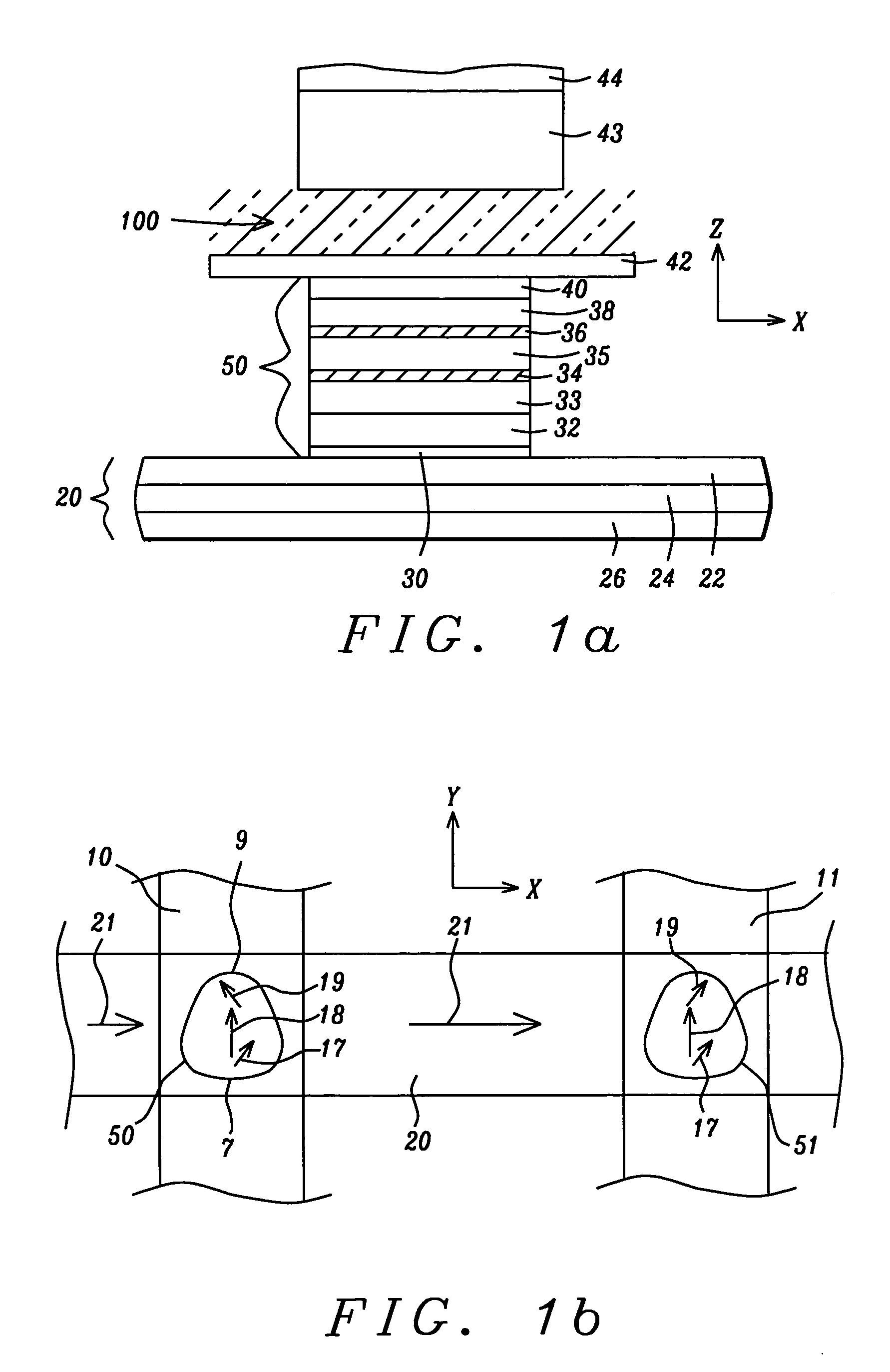
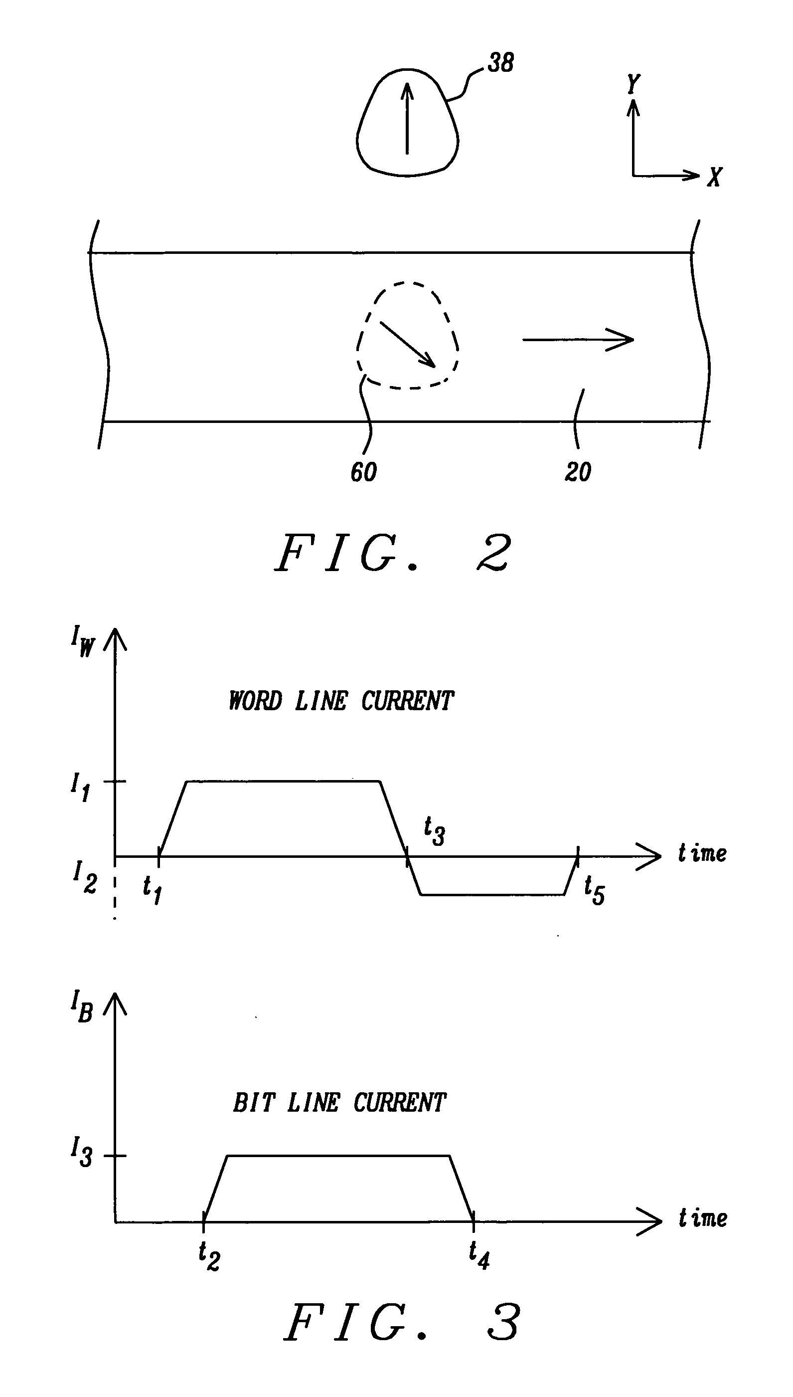
[0040]The preferred embodiment of the present invention provides an MTJ MRAM cell and its method of use, or an MRAM array of such cells, in which the required switching current in the bit line can be reduced, the bit state of the cell rendered thermally stable between writing and rewriting and the cells can be locked or unlocked in accordance with whether or not they have been selected to be written upon, all by the addition of a thin adjacent soft magnetic layer formed on the bit line which couples magnetostatically to a proximal free layer of the MTJ cell. The preferred embodiment also teaches a sequence of word and bit line currents that rewrite the MTJ MRAM cells in accord with the objects of the invention.

[0041]Referring back to FIG. 1a there is shown in a schematic vertical cross-sectional view (in the xz-plane) the general configuration of the MRAM cell of the present invention. The MTJ element (50), which can have a horizontal cross-sectional shape to provide a magnetic anis...


PUM


Abstract

An MTJ MRAM cell element, whose free layer has a shape induced magnetic anisotropy, is formed between orthogonal word and bit lines. The bit line is a composite line which includes a high conductivity current carrying layer and a soft adjacent magnetic layer (SAL). During operation, the soft magnetic layer concentrates the magnetic field of the current and, due to its proximity to the free layer, it magnetically couples with the free layer to produce two magnetization states of greater and lesser stability. During switching, the layer is first placed in the less stable state by a word line current, so that a small bit line current can switch its magnetization direction. After switching, the state reverts to its more stable form as a result of magnetostatic interaction with the SAL, which prevents it from being accidentally rewritten when it is not actually selected and also provides stability against thermal agitation.

Description

BACKGROUND OF THE INVENTION[0001]1. Field of the Invention[0002]This invention relates to the design and fabrication of a magnetic tunnel junction (MTJ) MRAM array, particularly to a design for locking (creating a stable magnetization state) un-selected array devices and unlocking (creating a less stable magnetization state) selected array devices.[0003]2. Description of the Related Art[0004]The magnetic tunnel junction (MTJ) basically comprises two electrodes, which are layers of ferromagnetic material, separated by a tunnel barrier layer, which is a thin layer of insulating material. The tunnel barrier layer must be sufficiently thin so that there is a probability for charge carriers (typically electrons) to cross the layer by means of quantum mechanical tunneling. The tunneling probability is spin dependent, however, depending on the availability of tunneling states with different electron spin orientations. Thus, the overall tunneling current will depend on the number of spin-up...

Claims


Application Information

Patent Timeline
Patent Type & Authority Patents(United States)
IPC IPC(8): H01L29/82H01L27/105G11C11/16H01L21/8246H01L43/08
CPCG11C11/16G11C11/15
Inventor GUO, YIMINWANG, PO-KANGSHI, XIZENGMIN, TAI
Owner HEADWAY TECH INC
Why Eureka
Try Eureka