Optical transmission link including raman amplifier

a technology of optical transmission link and amplifier, which is applied in the direction of optical elements, multiplex communication, instruments, etc., can solve the problems of reducing the strength of optical signals, reducing the insertion loss of edfa, and reducing the detection efficiency of optical signals over background nois

Inactive Publication Date: 2003-08-05
JDS UNIPHASE CORP
View PDF11 Cites 37 Cited by
  • Summary
  • Abstract
  • Description
  • Claims
  • Application Information

AI Technical Summary

Problems solved by technology

When optical signals are transmitted over great distances through optical fibers, attenuation within the fibers reduces the optical signal strength.
Therefore, detection of the optical signals over background noise becomes more difficult at the receiver.
Also, because the EDFA is spliced into the fiber as a separate component, insertion losses are typically higher with an EDFA than with a Raman amplifier.
Inaccuracies in monitoring pump powers and changes in the insertion loss of optical components prior to combining the laser beams limit the accuracy with which the power in each polarization can be accurately controlled.

Method used


Image

  • Optical transmission link including raman amplifier
  • Optical transmission link including raman amplifier
  • Optical transmission link including raman amplifier

Examples


Embodiment Construction

The following discussion of the embodiments of the invention directed to an optical transmission system employing a Raman amplifier having a depolarized pump source is merely exemplary in nature and is not intended to limit the invention, or its applications or uses.

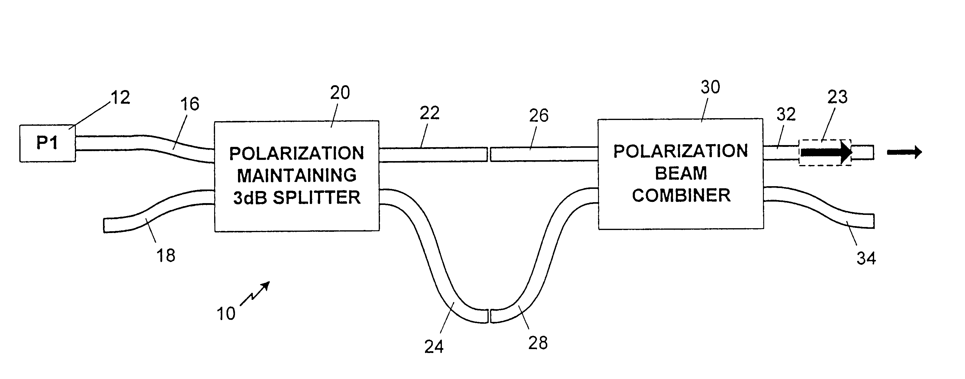
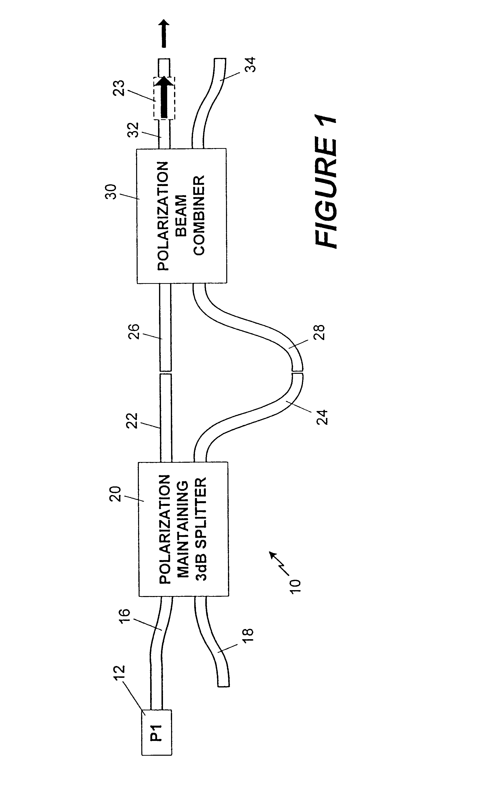
Shown in FIG. 1 is a first embodiment of a depolarized optical pump 10 for a Raman amplifier, according to the present invention, including an optical pump source 12, such as a semiconductor laser. The optical source 12 has a polarized output, and is labeled P1. The source 12 may be grating stabilized and operates in the "coherence collapse" mode. That is, the wavelength of light from the source 12 is preferably well controlled and has a coherence length that is relatively short. Preferably, the source 12 has a coherence length of less than one meter, with longitudinal modes having a line width on the order of one gigahertz or more. The source 12 is linearly polarized along one of the polarization axes of a polarization ...


PUM


Abstract

An optical transmission system that employs a Raman amplifier including a Raman pump for introducing depolarized pump light into the fiber. The pump includes an optical source generating a polarized optical pump signal, an optical splitter that splits the pump signal into a first pump portion and a second pump portion, and a beam combiner that combines the first pump portion and the second pump portion into the depolarized pump light. Further, the pump includes a delay device, such as a length of fiber, that causes the first pump portion to propagate farther from the beam splitter to the beam combiner than the second pump portion. The length of fiber is longer than the coherence length of the pump signal.

Description

1. Field of the InventionThis invention relates generally to an optical fiber link including a Raman fiber amplifier that employs a depolarized pump source and, more particularly, to an optical communications system including a fiber transmission link having a Raman amplifier that employs a depolarized pump source.2. Discussion of the Related ArtOptical communications systems employ optical transmission fibers to transmit optical signals carrying information over great distances. An optical fiber is an optical waveguide including a core having one index of refraction surrounded by a cladding having another, lower, index of refraction so that light signals propagating down the core at a certain angle of incidence are trapped therein. Typical optical fibers are made of high purity silica including certain dopant atoms that control the index of refraction of the core and cladding.The optical signals are separated into optical packets to distinguish groups of information. Different tech...

Claims


Application Information

Patent Timeline
Patent Type & Authority Patents(United States)
IPC IPC(8): G02B6/34G02B6/42G02B6/26G02B6/28G02B6/27H04B10/17
CPCG02B6/264G02B6/42H04B10/2916G02B6/274G02B6/2786G02B6/2861G02B6/4206G02B6/4213H01S3/094073H01S3/302H04J14/0221
Inventor FIDRIC, BERNARD G.SANDERS, STEVENDOMINIC, VINCENT G.
Owner JDS UNIPHASE CORP
Why Eureka
Try Eureka