Method and apparatus for controlled heating of adsorbent materials

a technology of adsorbent materials and controlled heating, which is applied in the direction of electric/magnetic/electromagnetic heating, dispersed particle separation, separation processes, etc., can solve the problems of high fuel consumption, high operating cost, and inability to achieve practical approaches, so as to minimize the problem of temperature control

Inactive Publication Date: 2003-08-19
HAROLD R COWLES
View PDF12 Cites 12 Cited by
  • Summary
  • Abstract
  • Description
  • Claims
  • Application Information

AI Technical Summary

Benefits of technology

It is therefore an object of the present invention to provide a method and apparatus for minimizing the temperature control problems associated with direct electric heating of activated carbon, and other conductive materials, in a columnar device--regardless of diameter.
The present invention incorporates a method and apparatus for heating adsorbent materials through the conduction of electrical current therethrough by using spaced electrodes positioned within a column of the adsorbent material within a vessel. In one embodiment, the size of the electrodes is varied such that the second electrode incorporates a cross-sectional area of about 50% of the cross-sectional area of the first electrode; as a result of the size differential, the current flowing through the adsorbent material column incorporates a substantial radial component that effectively establishes a relative uniformity of the current density through the column and thus establishes uniformity of the temperature resulting from the heating of the material by the current flow. In an alternative embodiment, the electrodes remain the same size, but a passive conductive element, or a "dummy electrode" is positioned between the active electrodes such that the electrical current carrying capacity of this passive electrode alters the current density along the cross-section of the material column. As a result, the current density is rendered more uniform and the temperature of the material across a transverse section of the column is rendered more uniform. The present invention eliminates the radial temperature variations resulting from current heating of the adsorbent material in a vessel that, as described above, is present in prior art systems attempting to heat the adsorbent material by the application of a potential across a column of the material to induce an electrical current therethrough and thus heat the material.

Problems solved by technology

VOC's are of concern, due not only to their direct toxicity in the vapor phase, but also because they can be photochemically reactive and lead to ground level ozone increases and increases in other gas phase irritants.
Reducing VOC's at the source is sometimes an option, but there are many processes for which this approach is not practical.
So called "oxidation" equipment is effective at destruction of VOC's, but has several inherent drawbacks.
These include high operating costs, high fuel consumption, and high levels of secondary pollutant generation.
Therefore, some of the same issues still apply.
A limitation of the device described in U.S. Pat. No. 5,089,457, and others of its kind, is that it does not solve the intrinsic problems associated with the heating of carbon in a columnar configuration, using electricity applied to the carbon itself.
Those skilled in the art are aware that the application of electricity to activated carbon, and the heating which results, renders the method prone to the formation of localized hot spots.
When electricity is applied, uneven heating occurs, due to the unpredictable and variable nature of the aforementioned items.
As pointed out in the '457 patent, the radius of the columnar vessel must be limited to seventy-five particle diameters or less; otherwise, the system cannot maintain temperature control, and the intended function of the entire device is lost.
This problem makes scale up to more practically sized systems impossible.
In practice, even a columnar device with the seventy-five particle diameter limit of the radius suffers from localized heating problems.
The difference becomes more severe as the diameter of the heating device increases, and as the temperature becomes higher.

Method used


Image

  • Method and apparatus for controlled heating of adsorbent materials
  • Method and apparatus for controlled heating of adsorbent materials
  • Method and apparatus for controlled heating of adsorbent materials

Examples


Embodiment Construction

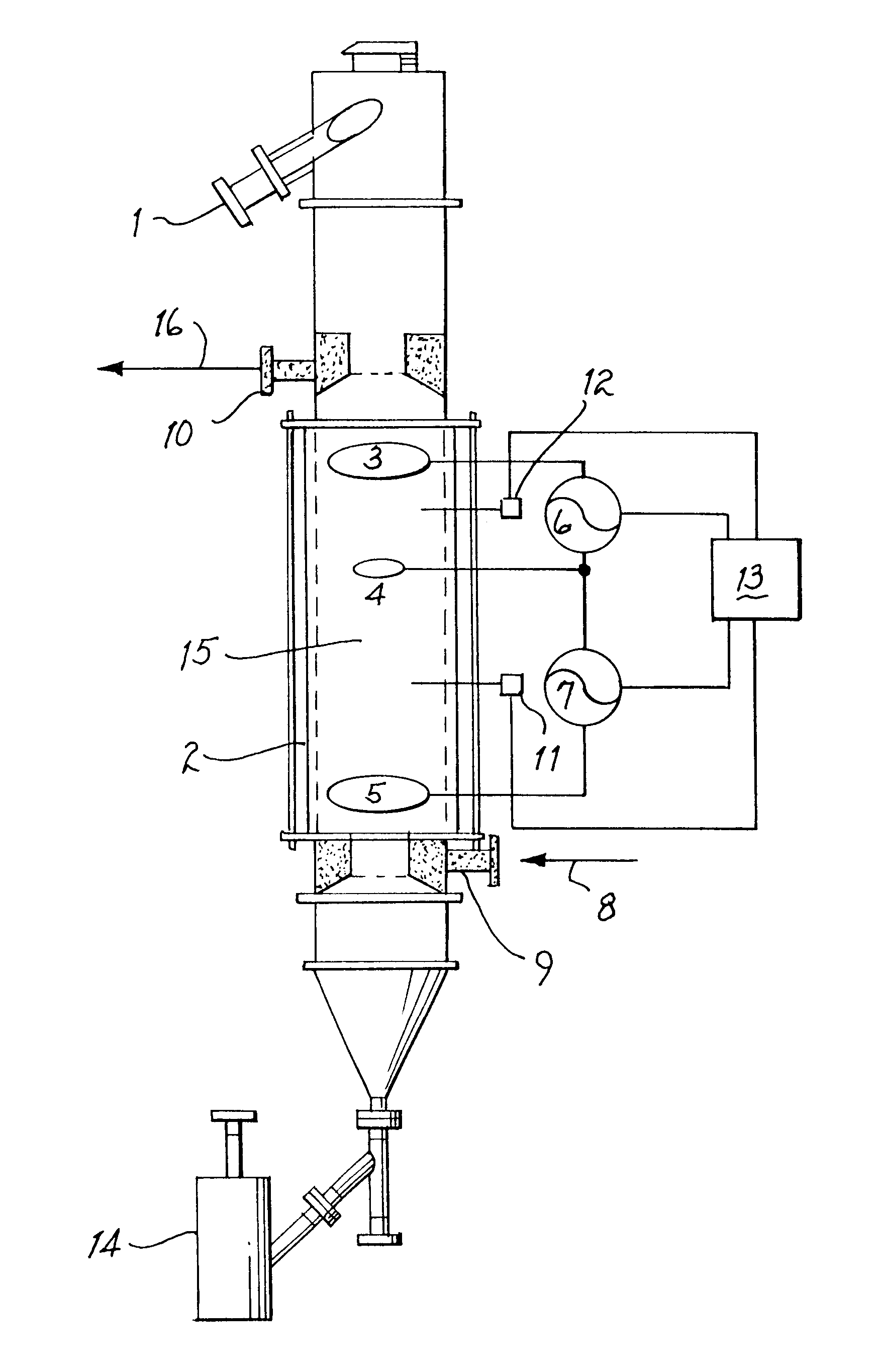
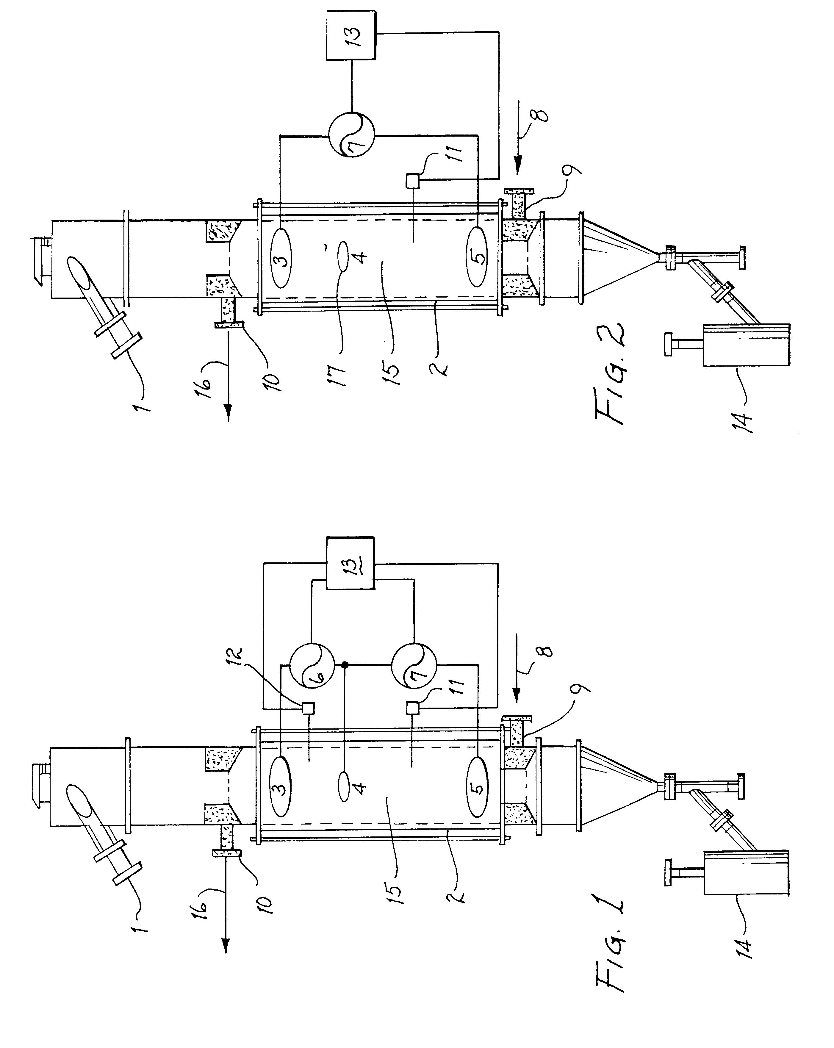
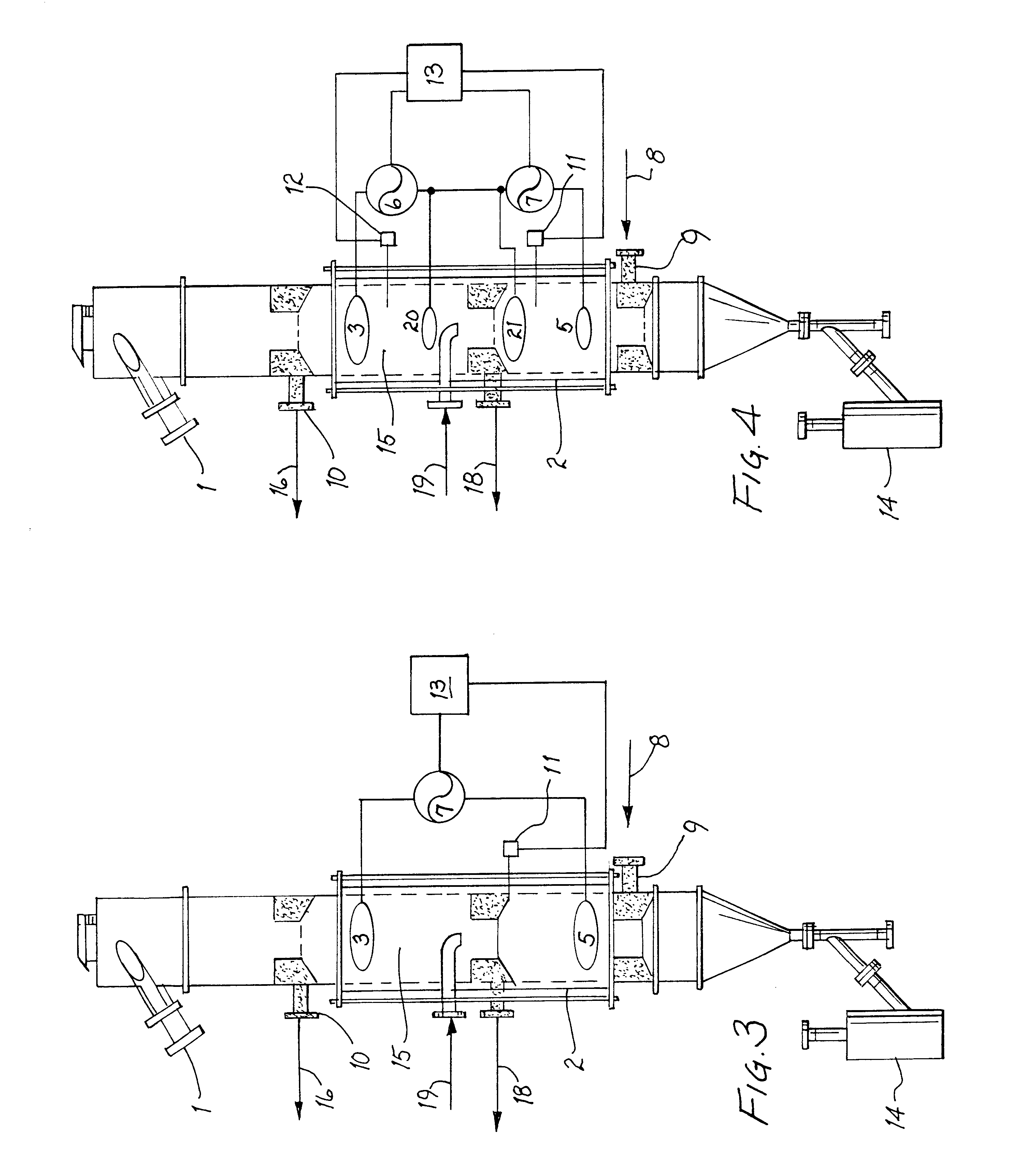
Referring to FIG. 1, adsorbent material enters a regeneration / reactivation vessel at the inlet 1 thereof. The regeneration vessel may be a cylindrical vessel constructed of non-electrical conducting material such as a ceramic, or may be formed of any material having an electrical insulating lining. Sufficient adsorbent material is provided such that the column of material in the vessel is always full. The carbonaceous adsorbent is caused to flow downward through the column at a controlled rate, as dictated by the operation and settings of adsorbent removal device 14. While the present invention is described in terms of carbonaceous adsorbent, and while such adsorbent is the most common used for the removal of VOC's in gas streams, other adsorbent materials are appropriate provided they are capable of being heated by electrical current passing therethrough. The electrical current may be an AC or DC current. In due course, the adsorbent flows through electrically non-conductive column...


PUM

PropertyMeasurementUnit
boiling pointsaaaaaaaaaa
temperatureaaaaaaaaaa

Abstract

A method and apparatus for controlling the heating of adsorbent materials in a vessel including the utilization of electrodes in direct contact with the adsorbent material to induce a current in the material. The electrical contacts are spaced apart and receive a potential for inducing the electrical current; one of the electrodes is a different size to thereby induce a radial component in the electrical current to thus modify the current density flowing through the adsorbent material as the current traverses the distance between the electrodes. The resulting modified current density causes the temperature gradient across the transverse section of the vessel to decrease, thus rendering the temperature more uniform across the vessel.

Description

The present invention relates to means for effectively removing Volatile Organic Compounds (VOC's) from various industrial gases, and more particularly to a method and apparatus to facilitate the removal of such compounds trapped on or in adsorbent materials that have previously been utilized for the removal of such VOC's from a contaminated air stream. More specifically, the present invention relates to a novel method and apparatus for heating such adsorbent materials to effect the removal of adsorbed VOC's to permit the reuse of such adsorbent material; further, the invention is directed to a method and apparatus that may be utilized to reactivate adsorbent material when such material is an activated carbonaceous material.Many industrial processes give rise to exhaust gases which contain volatile organic compounds (VOC's). VOC's are of concern, due not only to their direct toxicity in the vapor phase, but also because they can be photochemically reactive and lead to ground level o...

Claims


Application Information

Patent Timeline
Patent Type & Authority Patents(United States)
IPC IPC(8): B01D53/04
CPCB01D53/0407B01D2257/708B01D2259/40096
Inventor COWLES, HAROLD R.STANLEY, WILLIAM J.CUEMAN, CHRISTOPHER M.
Owner HAROLD R COWLES
Why Eureka
Try Eureka