Cup-type plating apparatus and method for plating wafers

a technology of plating apparatus and wafer, which is applied in the direction of coating, manufacturing tools, liquid/solution decomposition chemical coating, etc., can solve the problems of increasing the amount of plating solution mist, increasing the probability of contamination on the surface of the wafer, and generating contamination in the clean room

Inactive Publication Date: 2003-08-26
ELECTROPLATING ENGINEERS OF JAPAN LTD
View PDF7 Cites 6 Cited by
  • Summary
  • Abstract
  • Description
  • Claims
  • Application Information

AI Technical Summary

Benefits of technology

In the cup-type plating apparatus according to the present invention, since the plating solution flowing out of the plating tank is in a state isolated from the outer space, that is, a state separated from the space in which the surface (the rear of the surface to be plated) of the wafer placed on the wafer support is exposed, the contamination on the surface of the wafer due to the mist of the plating solutions can be prevented.
In the cup-type plating apparatus according to the present invention, preferably, the solution-outlet path passes through the interior of the wall of the tank from the solution-outlet port provided on the side of the inner periphery of the wall of the tank, which constructs the plating tank. Thus, the solution-outlet path in which the plating solution can pass through is provided in the interior of the wall of the tank, which constructs the plating tank, so that the plating solution flowing out of the solution-outlet port provided on the inner periphery of the wall of the tank is isolated from the outer space. Accordingly, a space for providing the solution-outlet path on the outside of the plating tank is not required, and the cup-type plating apparatus itself can be made compact. It is particularly effective when constructing a plating unit having a plurality of the cup-type plating apparatuses.
In order to reliably prevent the contamination on the surface of the wafer due to the mist of the plating solutions, preferably, a shutting means capable of closing the opening of the plating tank is provided. In the cup-type plating apparatus, while plating is performed in such a manner that the wafer which is placed on the wafer support provided along the opening of the plating tank is successively replaced, the opening of the plating tank is in an opened state during replacement. At this time, the mist of the plating solutions leaks a little from the opening into the outer space. When replacing of the wafer is completed in a relatively short time, that is, the time of opening the opening is short, it has little effect on the contamination on the surface of the wafer; however, when replacing of the wafer requires a long time, that is, when the opening is opened for a long time, the amount of mist of the plating solutions which leaks out is increased, and accordingly, there is a fear that it exerts an influence on the contamination on the surface of the wafer. Therefore, when the opening of the plating tank is closed when necessary by the shutting means capable of closing the opening of the plating tank, the contamination on the surface of the wafer due to the mist of the plating solutions can be further reliably prevented.

Problems solved by technology

In this case, a large amount of the mist of the plating solutions is likely to be generated at a time due to the plating solution flowing out of a plurality of the plating tanks, and consequently, the contaminant on the surface of the wafer is likely to be increased.
Therefore, when no measures against the mist of the plating solutions is taken, for instance, when a large amount of mist of the plating solutions exists in the plating process, it may leak into the clean room to generate contamination in the clean room; and, accordingly, it is not preferable for manufacturing wafers.
When replacing of the wafer is completed in a relatively short time, that is, the time of opening the opening is short, it has little effect on the contamination on the surface of the wafer; however, when replacing of the wafer requires a long time, that is, when the opening is opened for a long time, the amount of mist of the plating solutions which leaks out is increased, and accordingly, there is a fear that it exerts an influence on the contamination on the surface of the wafer.

Method used


Image

  • Cup-type plating apparatus and method for plating wafers
  • Cup-type plating apparatus and method for plating wafers
  • Cup-type plating apparatus and method for plating wafers

Examples


Embodiment Construction

A preferred embodiment of a cup-type plating apparatus according the present invention is described hereinbelow.

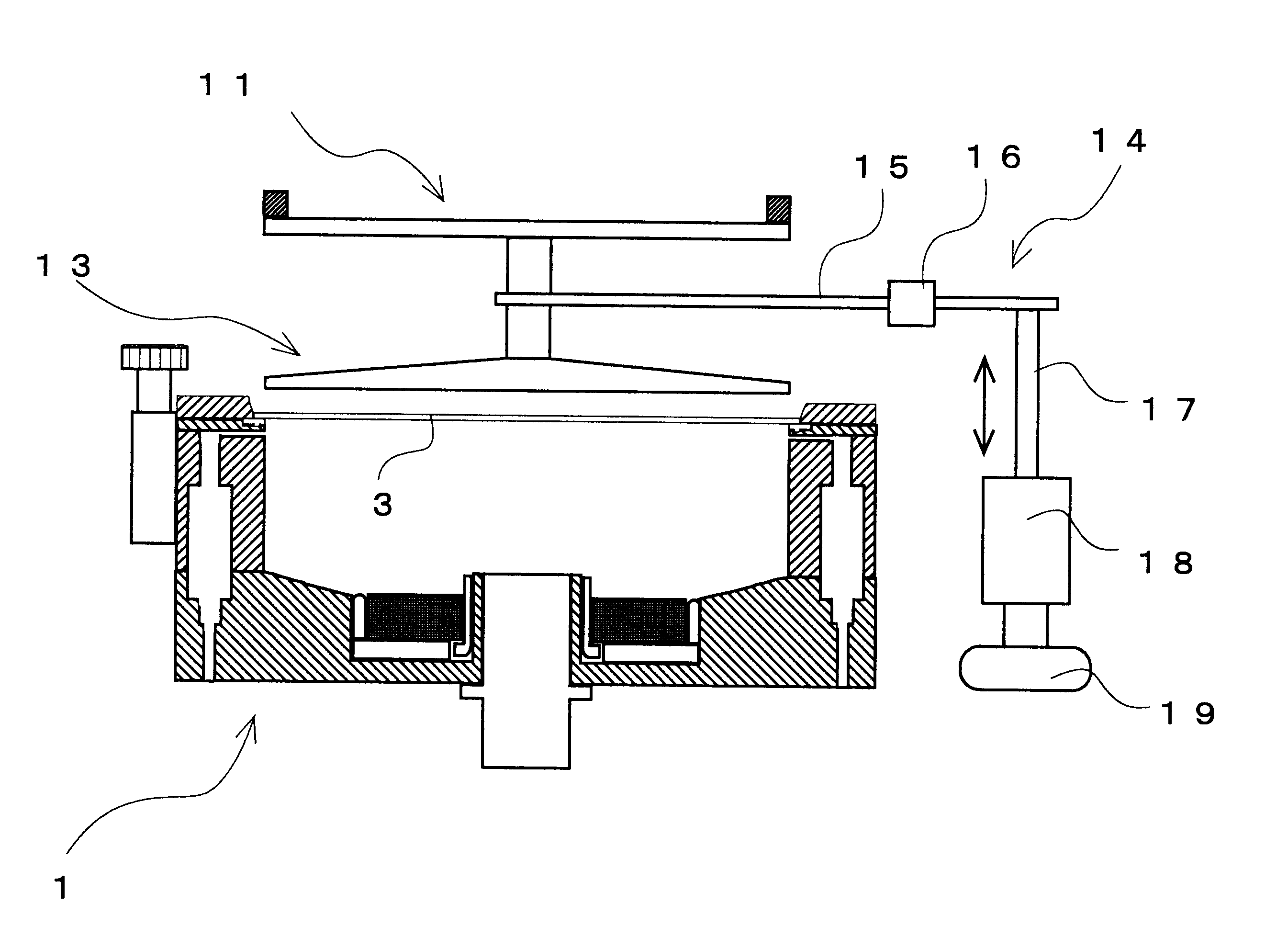
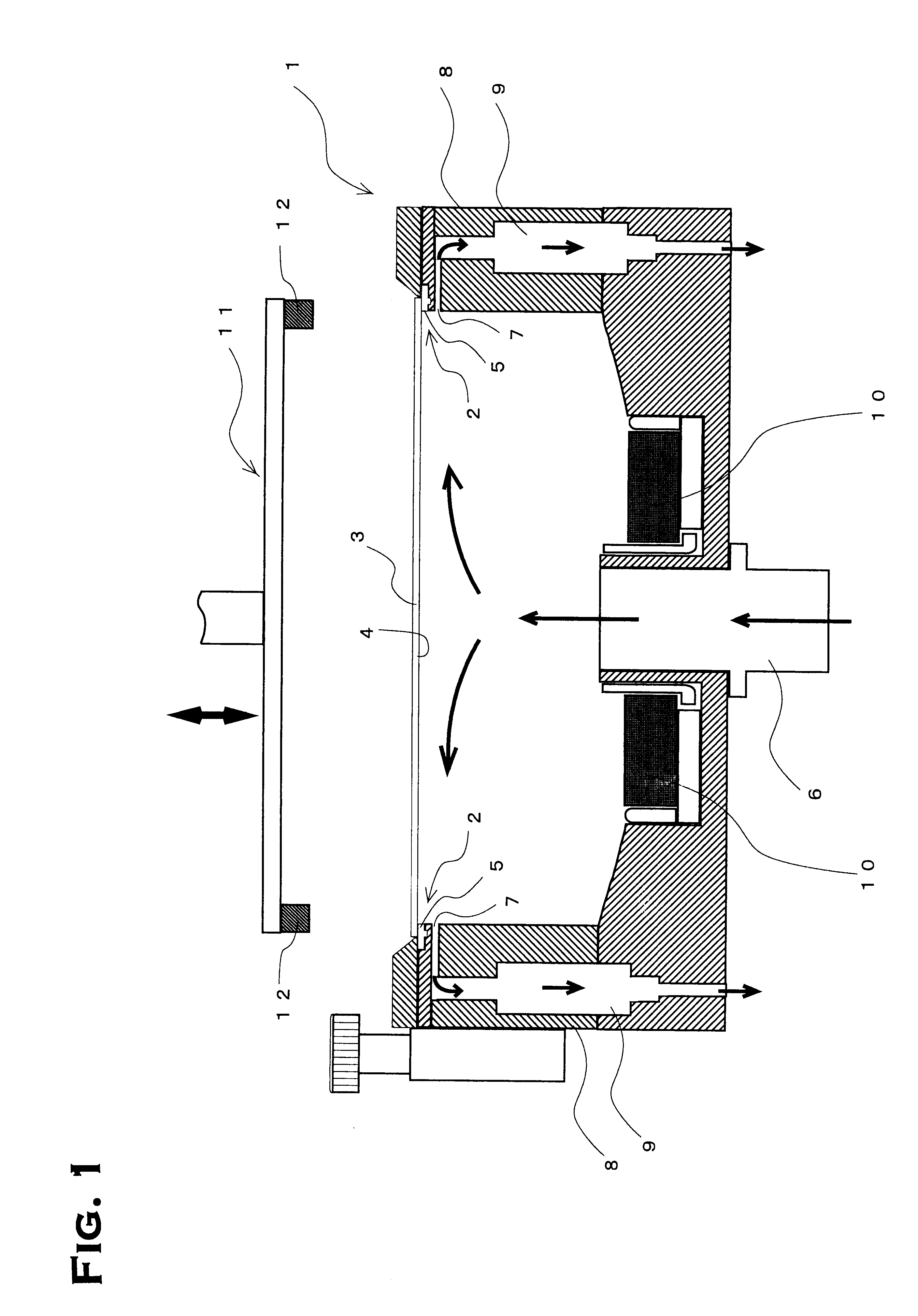
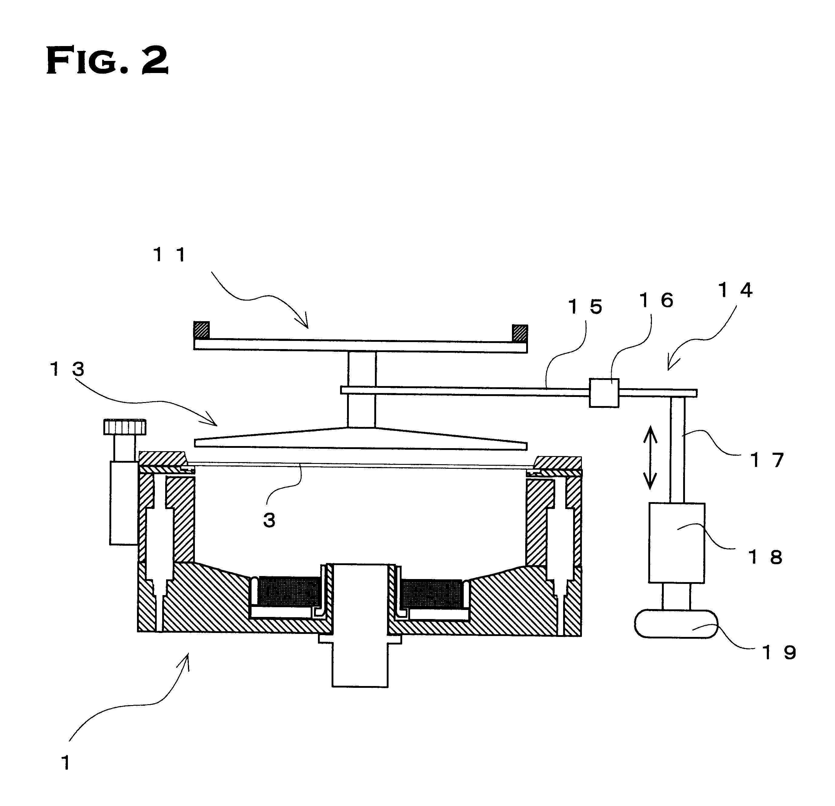
FIG. 1 shows a schematic sectional view of a cup-type plating apparatus in the embodiment. As shown in FIG. 1, the cup-type plating apparatus in the embodiment includes a wafer support 2 along an opening at the top of a plating tank 1, wherein a wafer 3 is placed on the wafer support 2, and plating is performed to a surface 4 of the wafer 3, which is to be plated. The wafer support 2 has a seal packing 5 being brought into contact with the periphery of the placed wafer 3 and having a ring cathode disposed thereon. In addition, a drawing of the ring cathode is omitted.

The plating tank 1 has a solution supply pipe 6 provided at the center of the bottom thereof. A solution-outlet port 7 is provided at a position below the wafer support 2 so that a plating solution supplied via the solution supply pipe 6 by an upward-moving stream reaches the vicinity of the center of the surf...


PUM

PropertyMeasurementUnit
diameteraaaaaaaaaa
thicknessaaaaaaaaaa
current densityaaaaaaaaaa

Abstract

The present cup-type plating apparatus improves a conventional cup-type plating apparatus and prevents the surface of a wafer due to a mist of the plating solutions from being contaminated. A plating solution is supplied to a wafer which is placed on a wafer support provided along an opening at the top of a plating tank from a solution-supply port provided at the bottom of the plating tank by an upward-moving stream; the plating solution is made to flow out of a solution-outlet port provided for the plating tank; and plating is performed while the plating solution is brought into contact with a surface of the placed wafer, which is to be plated, wherein the solution-outlet port has a solution-outlet path in which the discharged plating solution is isolated from the outer space.

Description

1. Field of the InventionThe present invention relates to an apparatus for plating wafers for semiconductors, more particularly to a cup-type plating apparatus in which the wafer is placed on an opening of a plating tank and is subjected to plating.2. Description of the Related ArtRecently, various kinds of plating, for example, formation of a bump, are performed in the manufacturing process of wafers for semiconductors. A cup-type plating apparatus is known as one of the apparatuses for plating the wafer.In this cup-type plating apparatus, a plating solution is supplied to a wafer, which is placed on a wafer support provided along an opening at the top of a plating tank, via a solution-supply port provided at the bottom of the plating tank by an upward-moving stream, and flows out of a solution-outlet port provided for the plating tank; thus, plating is performed while bringing the plating solution into contact with a surface of the placed wafer to be plated.In the cup-type plating...

Claims


Application Information

Patent Timeline
Patent Type & Authority Patents(United States)
IPC IPC(8): C25D7/12C25D7/00C23C18/31H01L21/288
CPCC25D17/001C25D7/123H01L21/288
Inventor SAKAKI, YASUHIKO
Owner ELECTROPLATING ENGINEERS OF JAPAN LTD
Why Eureka
Try Eureka