Self-compensated transimpedance amplifier

a transimpedance amplifier and self-compensation technology, applied in amplifiers, amplifiers controlled by light, positive-feedback circuit arrangements, etc., can solve the problems of difficult maintenance of accurate cancellation, difficult tuning, and significant cost of large volume production, so as to maximize the bandwidth of scaler 30 and limit the compensation output bandwidth. , the effect of eliminating the tedious and costly procedure of tuning

a transimpedance amplifier and self-compensation technology, applied in amplifiers, amplifiers controlled by light, positive-feedback circuit arrangements, etc., can solve the problems of difficult maintenance of accurate cancellation, difficult tuning, and significant cost of large volume production, so as to maximize the bandwidth of scaler 30 and limit the compensation output bandwidth. , the effect of eliminating the tedious and costly procedure of tuning

US6611174B1Inactive Publication Date: 2003-08-26SHERMAN ADAM J

Image

  • Self-compensated transimpedance amplifier
  • Self-compensated transimpedance amplifier
  • Self-compensated transimpedance amplifier

Examples


Embodiment Construction

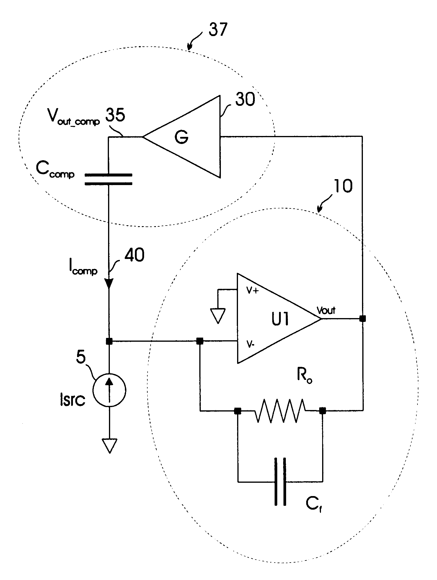
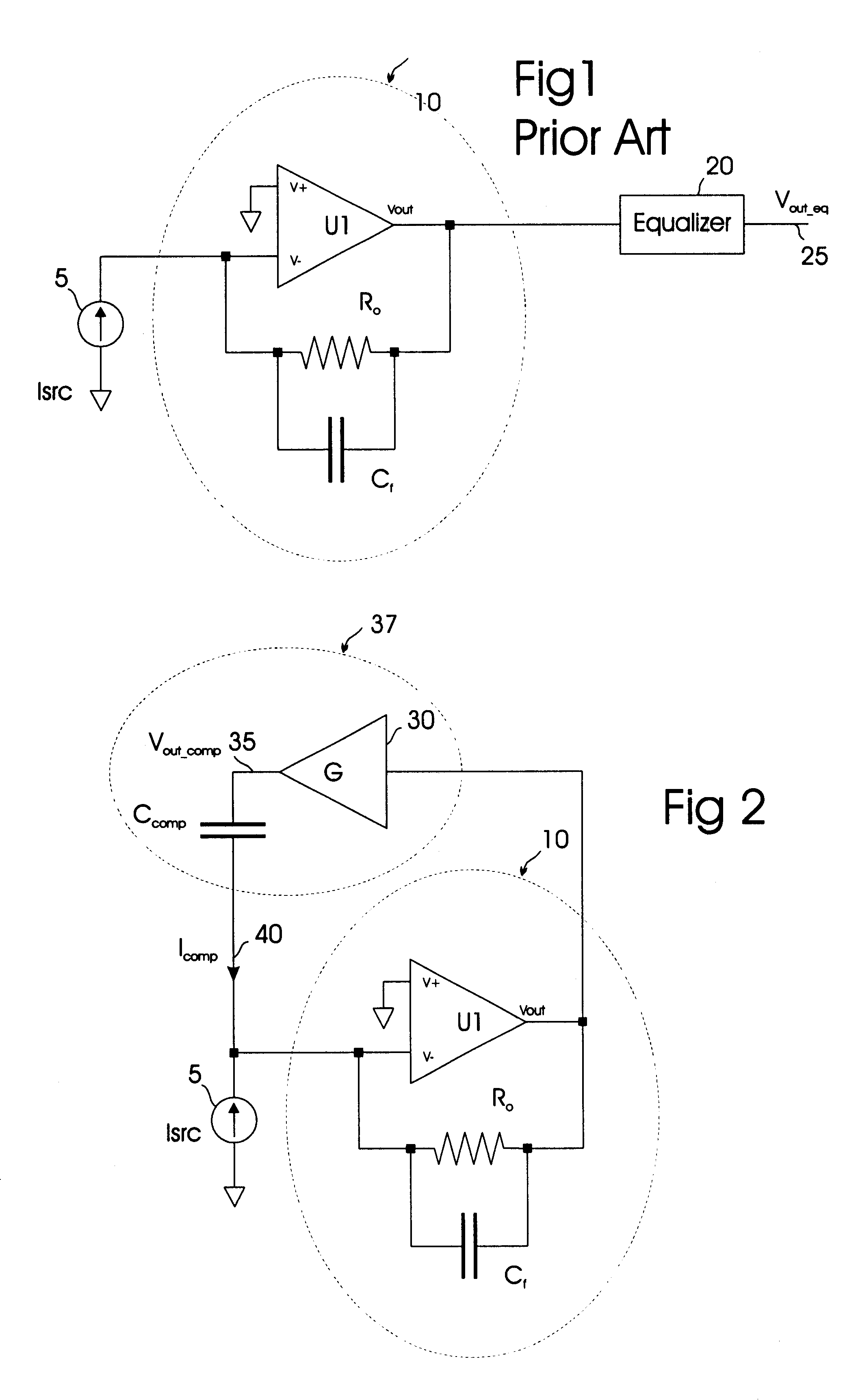
A typical embodiment of the SCTI amplifier of the present invention is applied to the IV converter is shown in FIG. 2. Referring to FIG. 2, IV converter 10 is shown with the addition a capacitive feedback means 37, in accordance with the present invention. Capacitive feedback means 37 takes as input Vout and produces a compensation current Icomp 40. Icomp 40 acts as an additional input to IV converter 10. An embodiment of capacitive feedback means 37 is shown in FIG. 2, where capacitive feedback means 37 comprises a voltage scaler 30 and a compensation capacitor Ccomp. Voltage scaler 30 is a prior art circuit well known to those skilled in the art that scales an input voltage by a positive or negative constant, providing this scaled input voltage as an output voltage. Scaler 30 takes as input Vout and produces an output voltage Vout_comp 35 by multiplying Vout by the scale factor G. Ccomp is connected between Vout_comp 35 and V-, thus providing Icomp 40 to IV converter 10. Therefore...


PUM


Abstract

A method to increase the bandwidth of a transimpedance amplifier using capactive feedback. The resultant amplifier maintains wide bandwidth, high linearity, low noise, and low input impedance independent of component variations. These characteristics greatly facilitate the economical measurement of small currents such as those arising from photodiodes and biological preparations.

Description

BACKGROUND OF INVENTION1. Field of the InventionThis invention relates to the measurement of small currents using a transimpedance amplifier. The present invention teaches a method to create a transimpedance amplifier that has wide bandwidth and very high linearity.2. Description of the Prior ArtThe IV ConverterFIG. 1 shows a common transimpedance amplifier circuit used to measure small currents know as an IV converter. Referring to FIG. 1, an IV converter 10 consists of an operational amplifier U1, a feedback resistor R.sub.o, and a feedback capacitance C.sub.f U1 has a non-inverting terminal V+, an inverting terminal V-, and an output terminal Vout. R.sub.o is connected between Vout and V- so that R.sub.o provides negative feedback around U1. C.sub.f is connected in parallels with R.sub.o and represents the sum of the stray capacitance across R.sub.o together with any additional feedback capacitance that parallels R.sub.o. An input current Isrc 5 that is to be measured is connecte...

Claims


Application Information

Patent Timeline
26 Aug 2003
Publication
US6611174B1
IPC
H03F3/08; H03F1/08; H03F1/14; H03F3/04
CPC
H03F1/14; H03F3/087
Inventors
SHERMAN, ADAM J.