It is therefore the object of the invention to specify a method for controlling the boost pressure, which makes the buildup of boost pressure more comfortable, but which also reacts quickly to sudden load demands.
In addition to specifying an absolute value of the measured value that is intended with the existing control, the measure according to the invention consists in detecting the gradient for this load-proportional measured value, meaning its change per time unit, and in specifying a
limit value for this load-proportional gradient. In the even that the
limit value is exceeded, the control returns the detected load-proportional gradient to the predetermined
limit value by adjusting the blow-off valve in the "open" direction and, depending on the design of the complete
system, by also reducing the load control of the engine. The load control intervention can be effected, for example, by adjusting the
throttle valve, but also with unconventional methods such as variable valve control times or a mixture control.
As a result, the driver can adequately react to the strong increase in the boost pressure, which results in an increase in the rotational moment of the engine. It is thus avoided that the driver is surprised by an excessively rapid increase in the boost pressure. The rapid increase causes an undesirably
high pressure in the air intake tract during the driver reaction time and thus a
power output that is not desired or expected by the driver and results, for example, in a
spinning of the drive wheels or a forward jump of the vehicle. The driver is given the opportunity to react to the increase in the engine moment with a reduction in the pedal load or even through dynamic driving actions (counter steering).
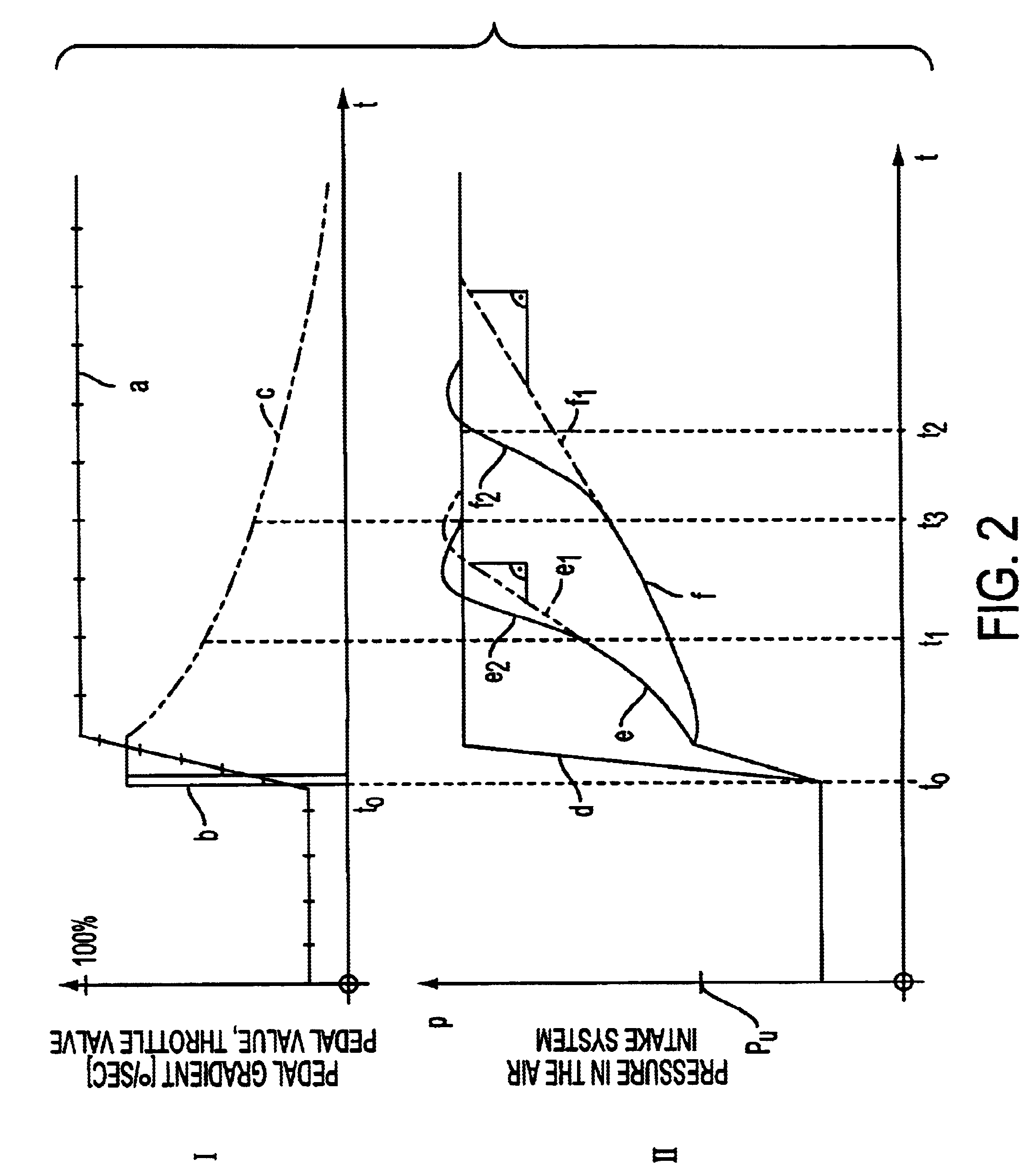
According to one embodiment of the invention, the pedal gradient is furthermore taken into account as a limit value for the load-proportional gradient. The term "pedal gradient" within the meaning of the invention relates to the change in the pedal position in dependence on the time. Thus, if the driver pushes down the pedal only slowly to increase the vehicle speed, or keeps it at a constant position, the driver expects only a slow change in the engine moment and the limit value selected for the load-proportional gradient must be small. If the pedal is pushed down rapidly, the driver expects a correspondingly rapid change in the engine moment. A large load-proportional gradient can be permitted without loss of comfort or safety.
According to another advantageous embodiment of the invention, the respective limit value is taken from the performance characteristic for the pedal gradient that is low-pass filtered in a negative direction. This link favorably takes into account the expectations of the driver. With a constant pedal value, meaning the pedal gradient is zero, the driver normally expects only a moderate change in the rotational moment, even if the pedal value is high. In contrast, if the pedal is pushed down quickly, the driver expects a rapid rotational moment increase that corresponds to the speed of the pedal movement. However, this increase is less and less the farther back the pedal movement for acceleration occurred. As a result of the low-pass filter for the
signal "pedal gradient," the
pressure increase in the air intake tract that is permitted by the engine control with increasing passage of time between the
signal and the response of the
turbocharger is lower than would actually be possible. As a result, it is avoided that the driver is surprised by an unexpected, sudden increase in the rotational moment. This value can be modified further in dependence on additional input variables.
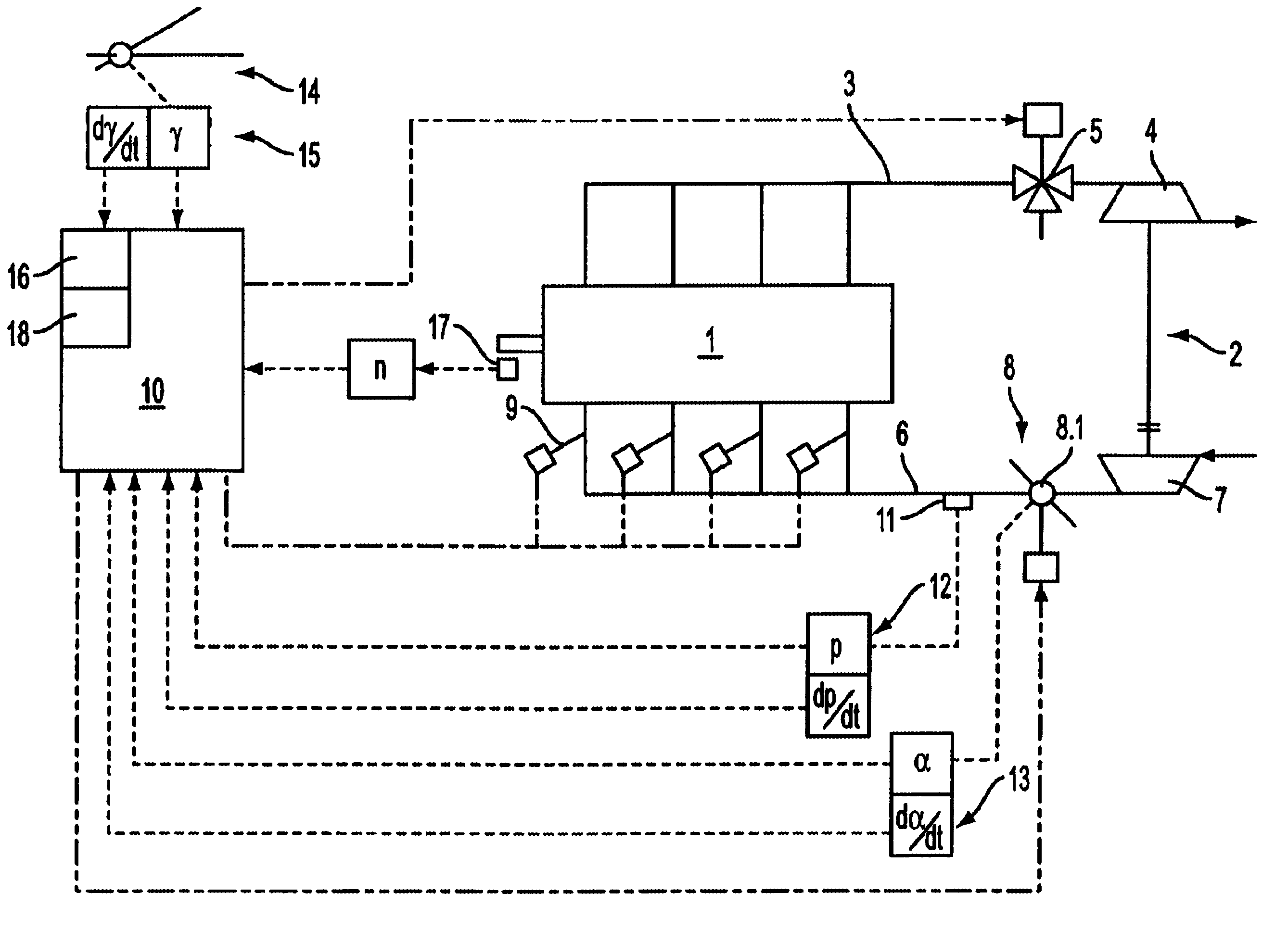
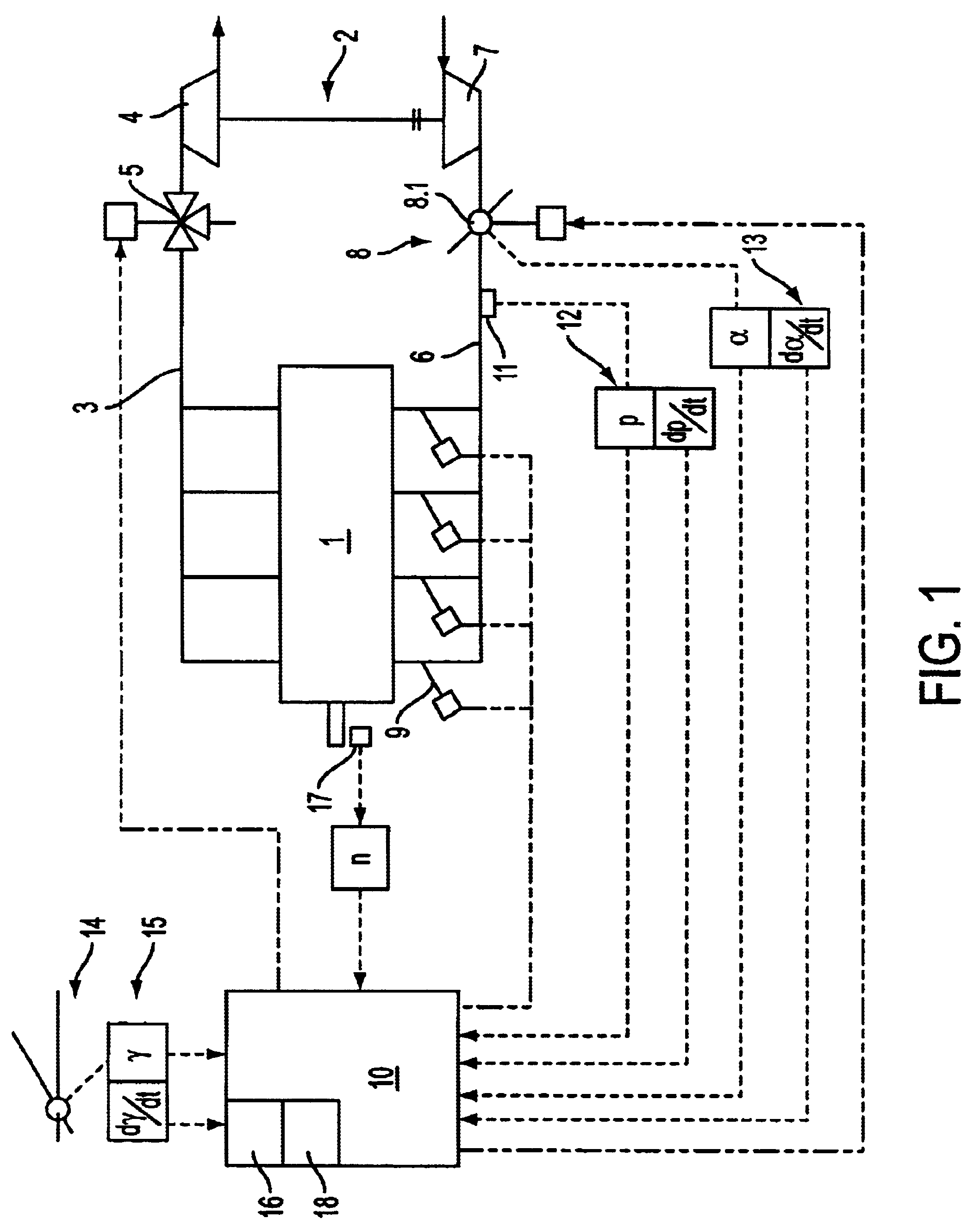
According to another advantageous embodiment of the invention, the boost pressure gradient in the air intake tract is detected as the load-proportional gradient. The
air mass flow in the air intake tract is proportional to the pressure in the air intake tract and also proportional to the load. As a result, the boost pressure gradient represents a load-proportional gradient that is directly connected to the respective control and regulation actions. If the driver demands a strong acceleration via the pedal position, then the increased
fuel supply causes the
piston-type
internal combustion engine to react by increasing the exhaust-gas energy, which leads to an increase in the boost pressure via the charging
turbine and the charger. By detecting the boost pressure gradients, the
time curve for the boost
pressure increase can be detected and, in case of an undesirably steep increase, the blow-off valve can be adjusted practically extrapolating in the opening direction, so that the increase will become less steep. As a result of the control behavior of the complete
system involving the piston-type
internal combustion engine and the turbocharger, a corresponding performance characteristic can be provided for the respective load condition and operating condition in the engine control. Thus, if the limit value for the boost pressure gradient that is respectively specified by the performance characteristic is reached, the blow-off valve can be correspondingly opened and the
energy supply to the charge turbine can be reduced. It is thus possible to have a sensitive guidance of the boost pressure increase in the air intake tract. In driving situations where the pedal movement leads to the assumption that the driver desires and expects this, the physically possible unsteady performance of the system can be demanded. In situations where it can be assumed that the driver does not expect considerable changes in the rotational moment, the system dynamic can be suppressed to a comfortable and secure measure.

