Method and apparatus for balancing

a technology of balancing and apparatus, applied in adaptive control, process and machine control, instruments, etc., can solve the problems of prone to imbalance failure and/or imbalance error, limited precision and reliability of relatively high-speed machine tool assemblies, and loss of significant revenues if "shut down"

Inactive Publication Date: 2003-09-09
LORD CORP
View PDF27 Cites 79 Cited by
  • Summary
  • Abstract
  • Description
  • Claims
  • Application Information

AI Technical Summary

Problems solved by technology

While these machine tool assemblies adequately create the desired parts, products, and/or other entities they are prone to imbalance failure and/or imbalance error.
Hence, the precision and reliability of these relatively high-speed machine tool assemblies is limited by the imbalance which exists and/or arises as the assembly is used (e.g. as the tool is engaging rotated and/or moved against the workpiece).
Similar types of unbalance or imbalance difficulties arise in the rotation and the utilization of relatively high-speed turbomachinery which is used in a variety of manufacturing and electrical power generation facilities and which causes the loss of significant revenues if "shut down" and/or disabled for even a relatively brief period of time.
While somewhat effective, these prior balancing devices and methodologies suffered from various drawbacks.
This "interruption" or "off line" balance was and remains relatively costly and highly inefficient.
So

Method used


Image

  • Method and apparatus for balancing
  • Method and apparatus for balancing
  • Method and apparatus for balancing

Examples


Embodiment Construction

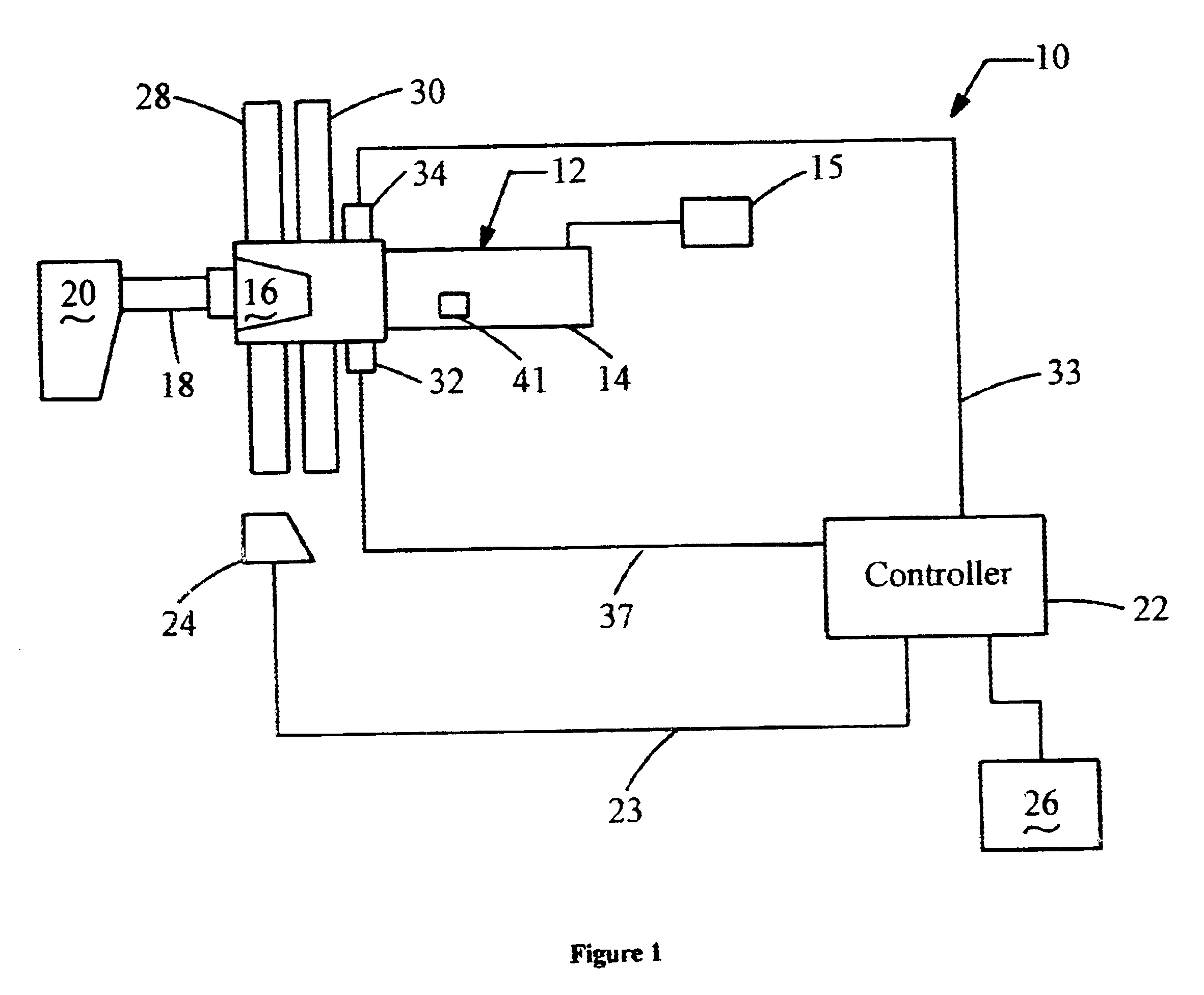
Referring now to FIG. 1 there is shown a balancing assembly 10 shown in operative and assembled relation with a typical and conventional tool assembly 12. Assembly 10, as shown, is made in accordance and operates in accordance with the preferred embodiment of the invention.

As shown, tool assembly 12 includes a moving or selectively rotatable spindle 14 having an integral tool holder 16 into which a tool 18 is removably placed. In operation, the movement and / or rotation of spindle 14 causes the tool 18 to move and / or rotate and to engage a workpiece 20 for the purpose of "machining" the workpiece 20 into some sort of desirable shape, size, and / or geometry. As earlier explained, tool assembly 12 is subject to unbalances which cause the tool 18 to perform imprecisely and undesirably and which causes the tool 18 and / or other portions of assembly 12 to fail and / or to become fatigued.

As shown, balancer assembly 10 includes a controller 22 which in one embodiment of the invention comprises...


PUM


Abstract

A balancer assembly 10 which automatically provides balancer limits, which achieves a balancing state while substantially minimizing short term vibration increases and which provides for multi-plane balancer dithering.

Description

(1) Field of the InventionThis invention generally relates to a method and an apparatus for balancing and more particularly to a method and to an apparatus for balancing a rotating machine tool and / or rotating / moving machine tool assembly.(2) Background of the InventionMachine tool assemblies are used to create and / or to form various parts, products, and other types of entities and / or apparatuses. Particularly, these apparatuses include tools which are usually and removably placed, by means of a tool holder, upon a rotating or moving spindle and which are adapted to engage a workpiece or other apparatus and to engagingly form the workpiece into a desired shape and size. While these machine tool assemblies adequately create the desired parts, products, and / or other entities they are prone to imbalance failure and / or imbalance error. Hence, the precision and reliability of these relatively high-speed machine tool assemblies is limited by the imbalance which exists and / or arises as the...

Claims


Application Information

Patent Timeline
IPC IPC(8): G01M1/22G01M1/36G01M1/00B23Q11/00
CPCG01M1/22G01M1/36
Inventor DYER, STEPHEN WILLIAM
Owner LORD CORP
Why Eureka
Try Eureka