Process for producing resonant tag

a technology of resonant tags and die stamping, which is applied in the direction of magnets, printed circuit assembling, magnetic bodies, etc., can solve the problems of metal foil and carrier sheets having to be separated with difficulty, and the die stamping is not so advantageous in other cases

Inactive Publication Date: 2003-09-16
NOVATRON ELECTRONICS HANGZHOU
View PDF32 Cites 58 Cited by
  • Summary
  • Abstract
  • Description
  • Claims
  • Application Information

AI Technical Summary

Benefits of technology

Still further, the present invention intends to provide resonant tags which can be readily manufactured and which have stable resonant characteristics.

Problems solved by technology

Thus, the die stamping is applicable to laminate a metal foil with strength to some degree on a solid base material, whereas the die stamping is not so advantageous for other cases.
Thus, that aluminum foil may be broken or the base sheet may be also stamped out during stamping out or transferring the foil, so that the resonant tag using the die stamping has not been put into practical use in the current state.
However, this process has such problems as (1) the additional step of laminating the metal foil on the carrier sheet is required; (2) the metal foil and the carrier sheet must be separated with difficulty; (3) when the stamped-out shape is discontinuous such as round, the separation between the stamped-out portion and the non stamped-out portion is difficult; and the like.
The protrusion transfer roll is often troublesome to be used as a die back-up roll for the die roll in that the stamping die and the protrusions must be aligned with each other, etc.
In these methods, however, there have been cases that when the thickness (line width) of a circuit-like coil is thin or when the distances between the neighboring lines becomes narrow, the lines are burnout or the lines are connected to each other at the manufacturing step or the lines connected to each other, resulting in producing inferior circuits.

Method used


Image

  • Process for producing resonant tag
  • Process for producing resonant tag
  • Process for producing resonant tag

Examples


Embodiment Construction

Under the above-mentioned conditions, the resonant tag of the present invention (Example) and the conventional resonant tag were manufactured and the performances of the manufactured resonant tags were compared.

The resonant tag of the Example is a resonant tag of the both-face coil type as shown in FIG. 4D. The Comparative Example is a resonant tag in one-face coil type as shown in FIG. 7.

The constitutions and properties are shown in Table 1.

As shown in Table 1, the resonant tag of the present invention has the similar resonant strength to that of the conventional resonant tag in spite that the number of winding coil is less.

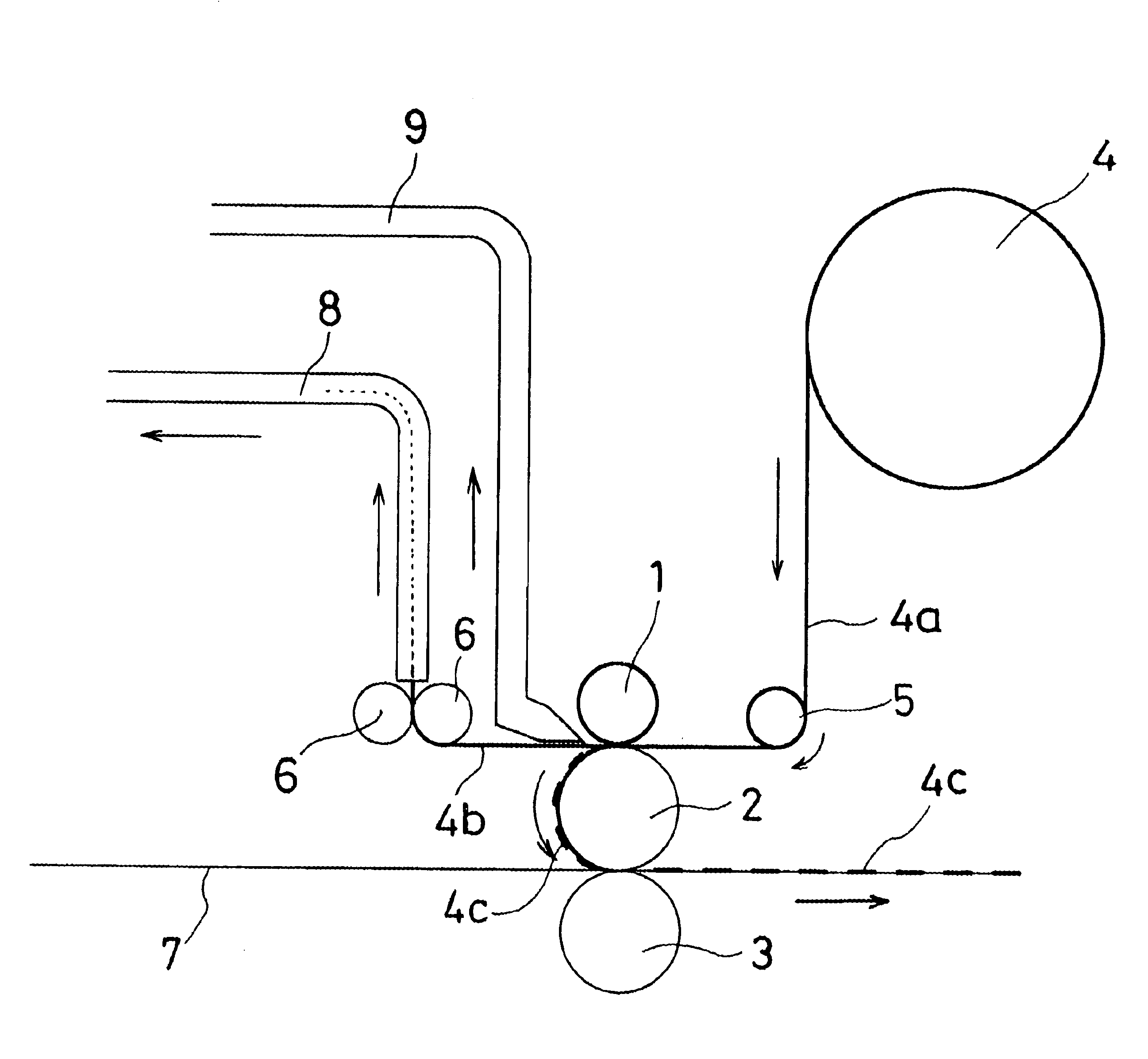
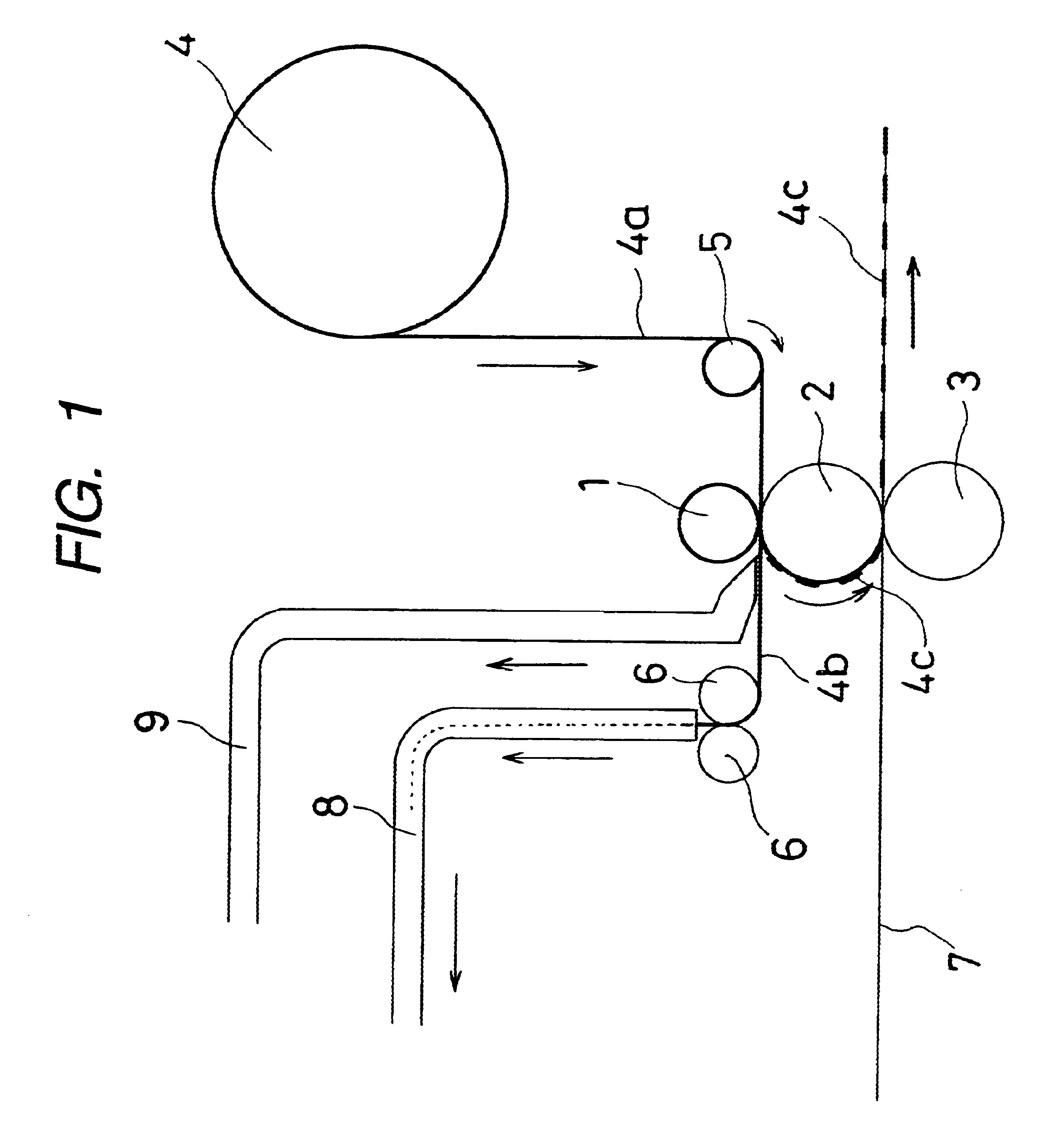
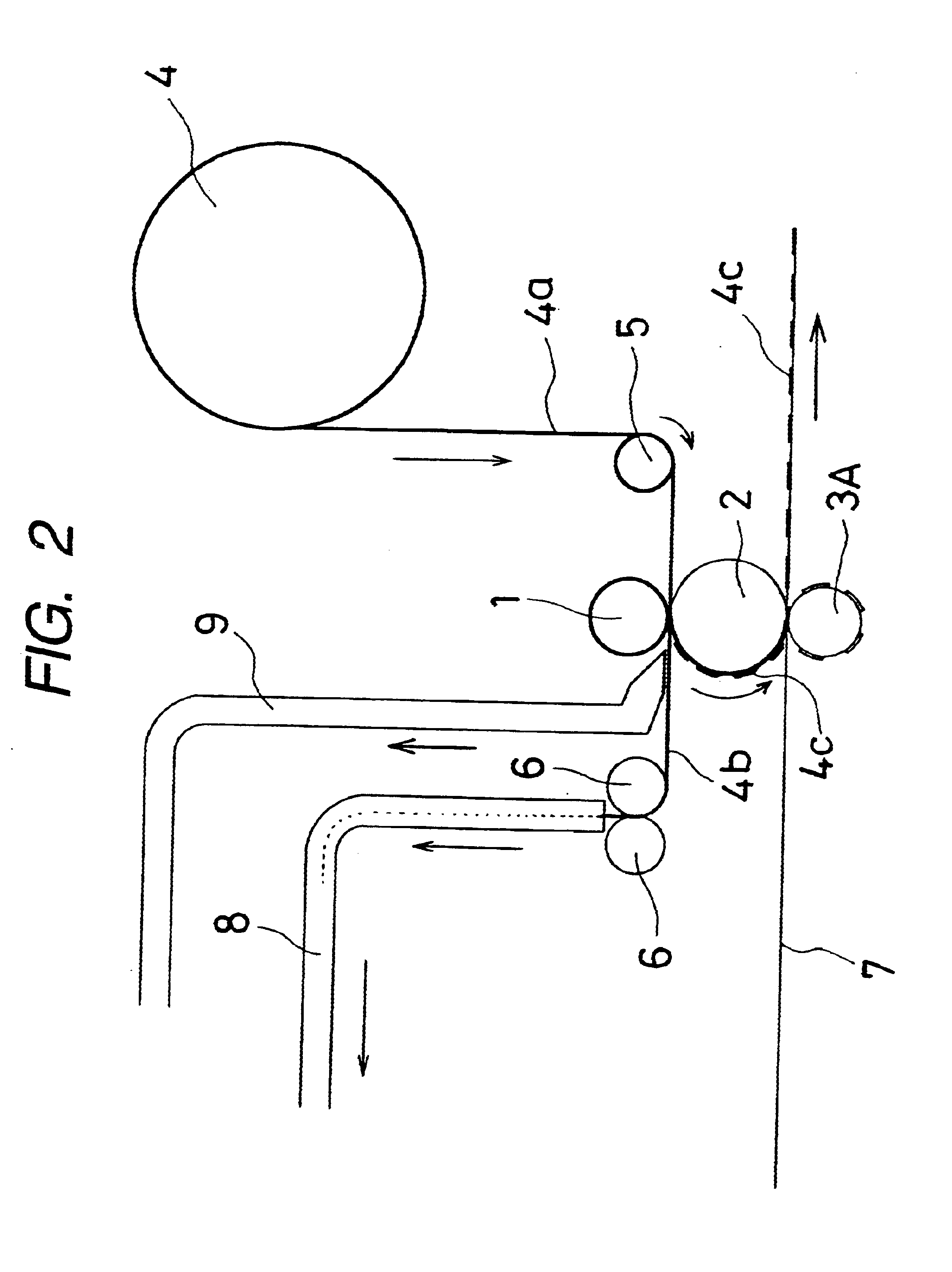
FIG. 6 is an exploded perspective view showing the constitution of the other Example of the resonant tag according to the present invention. The coil-shaped metal foils 4C.sub.1, 4C.sub.2 which are stamped out by the method of the present invention are adhered to the both faces of a dielectric sheet 53 and then, they are adhered to a base sheet 71.

In the constit...


PUM

PropertyMeasurementUnit
resonant frequencyaaaaaaaaaa
widthaaaaaaaaaa
thermal adhesionaaaaaaaaaa

Abstract

A process for producing a resonant tag, wherein a metal foil having a thermal adhesion adhesive applied to at least one face thereof is stamped out into a circuit-like shape and is adhered to a base sheet, the process comprising: stamping out the metal foil into a predetermined shaped metal foil portion (4c) while being passed through a die roll (1) having thereon a stamping blade with a predetermined shape and a transfer roll (2) in contact with the die roll (1) which functions also as a die back-up roll; holding this metal foil portion obtained by the stamping-out operation onto the surface of the transfer roll by suction holes formed in the transfer roll; and thermally adhering the stamped metal foil portion to the base sheet (7) in contact with the transfer roll (2) at its another face by an adhesive roll (3) in contact with the transfer roll through the base sheet. The present invention has such advantages as no damage to the base sheet since the stamping-out operation for the metal foil and the thermal adhesion operation thereof to the base sheet are carried out in separate positions, and no requirement of carrier sheet because the resultant metal foil portion obtained by the stamping-out operation is sucked and held onto the surface of the transfer roll.

Description

This application claims priority to Japanese Patent Application No. Hei 11-260466 filed Sep. 14, 1999 and is also related to Japanese Patent Application No. Hei 10-64465 filed Feb. 27, 1998.1. Field of the InventionThe present invention relates to a process for producing a resonant tag equipped with a resonant frequency circuit which resonates with a radio wave transmitted at a particular frequency from a detector.2. Description of the Related ArtAs is well known, resonant tag is a tag equipped with a resonant circuit which resonates with a radio wave transmitted at a particular frequency. Thus, when the resonant tag is brought into an area in which the radio wave of the particular frequency is transmitted, the resonant tag readily reacts to operate a buzzer or an alert lamp of a detector. Thus, to avoid shoplifting, the resonant tags are attached to goods and the like in department stores, discount stores, rental shops for video tapes, compact disk (CD) shops, etc.Basically, a reso...

Claims


Application Information

Patent Timeline
Patent Type & Authority Patents(United States)
IPC IPC(8): G08B13/24G06K19/077H01F41/04H01F5/00H05K3/04H05K3/02
CPCG06K19/07718G06K19/07749G08B13/242G08B13/2431G08B13/2437G08B13/244H01F5/003H01F41/041H05K3/041B32B2425/00Y10T29/49073Y10S428/901Y10T29/49018Y10T428/24917Y10T428/2817Y10T29/4913Y10T29/49155Y10T29/49016Y10T29/532Y10T29/49002B32B2519/02Y10T428/31681
Inventor UCHIBORI, SHINYAMIZUKAWA, TAKAAKIHATANAKA, YOSHINORI
Owner NOVATRON ELECTRONICS HANGZHOU
Why Eureka
Try Eureka