Solar collector pipe

a solar collector and collector pipe technology, applied in the field of solar energy collection, can solve the problems of inefficient energy collection of conventional solar water heating systems, inconvenient maintenance and repair, and inefficient solar energy collection and transfer. achieve the effects of convenient manufacture and assembly, high efficiency, and convenient maintenance and repair

Inactive Publication Date: 2003-09-16
GHELA MANU
View PDF35 Cites 31 Cited by
  • Summary
  • Abstract
  • Description
  • Claims
  • Application Information

AI Technical Summary

Benefits of technology

Therefore, it would be advantageous in the art to have a highly efficient solar collector which is easy to manufacture and assemble, is easy to maintain and repair, and is structured of inexpensive materials, thereby overcoming the aforementioned disadvantages of conventional solar heating systems. Embodiments of the present invention solve these problems through a solar collector pipe that directly conveys fluid to be heated and collects and transfers solar energy efficiently and directly to the internal fluid, thereby maximizing both the amount of energy transmitted to the internal fluid and the peak temperature attainable by that fluid.
Accordingly, the solar collector pipe of this invention has many advantages, one of which is that it is highly efficient. That is, by providing a transparent portion and a conduit portion (with an internal reflecting surface) with certain shapes, such as parabolic shapes, solar energy is appropriately directed to the absorbing portion, particularly if it is located along a vertical center axis of the solar collector pipe. Thus, fluid within the solar collector pipe may be heated directly by the solar energy transmitted through the transparent portion, as well as by reflected energy from the reflecting surface of the conduit portion and through heat transfer from the heat absorbing portion. Additionally, the solar collector pipe of the present invention is relatively inexpensive and easy to manufacture, assemble, maintain, and repair.

Problems solved by technology

These conventional solar water heating systems, however, have certain drawbacks.
Conventional systems are inefficient in energy collection.
That is, they do not collect and transfer solar energy efficiently and directly to the water.
Thus, whatever form the solar energy absorbing element may take (e.g. black, water-containing tube), it is inherently inefficient and is continually losing a significant portion of the absorbed energy by the well known mechanisms of convection, conduction and radiation.
The interaction of these heat loss mechanisms limits both the amount of energy transmitted by the absorber to the internal adjacent fluid and the peak temperature attainable by that fluid.
Conventional systems are also expensive to manufacture and difficult to install, requiring a substantial amount of labor on-site during installation, thereby resulting in a system which is difficult and expensive to maintain.
), often covering significant portions of the structure being heated, and are expensive (i.e. $6000-$10,000).
The size of the box presents a variety of problems.
A significant amount of space must be provided to house such components.
Furthermore, since such components are generally relatively heavy, the supporting structure must often be strengthened in some way to accommodate the excess weight of the components involved.
These solar energy collector systems, however, while often reduced in size, generally involve a combination of dissimilar structural elements which are often costly and complex.
This also leads to many of the disadvantages previously described in conjunction with the large flat pipe and box systems.

Method used


Image

  • Solar collector pipe
  • Solar collector pipe
  • Solar collector pipe

Examples


Embodiment Construction

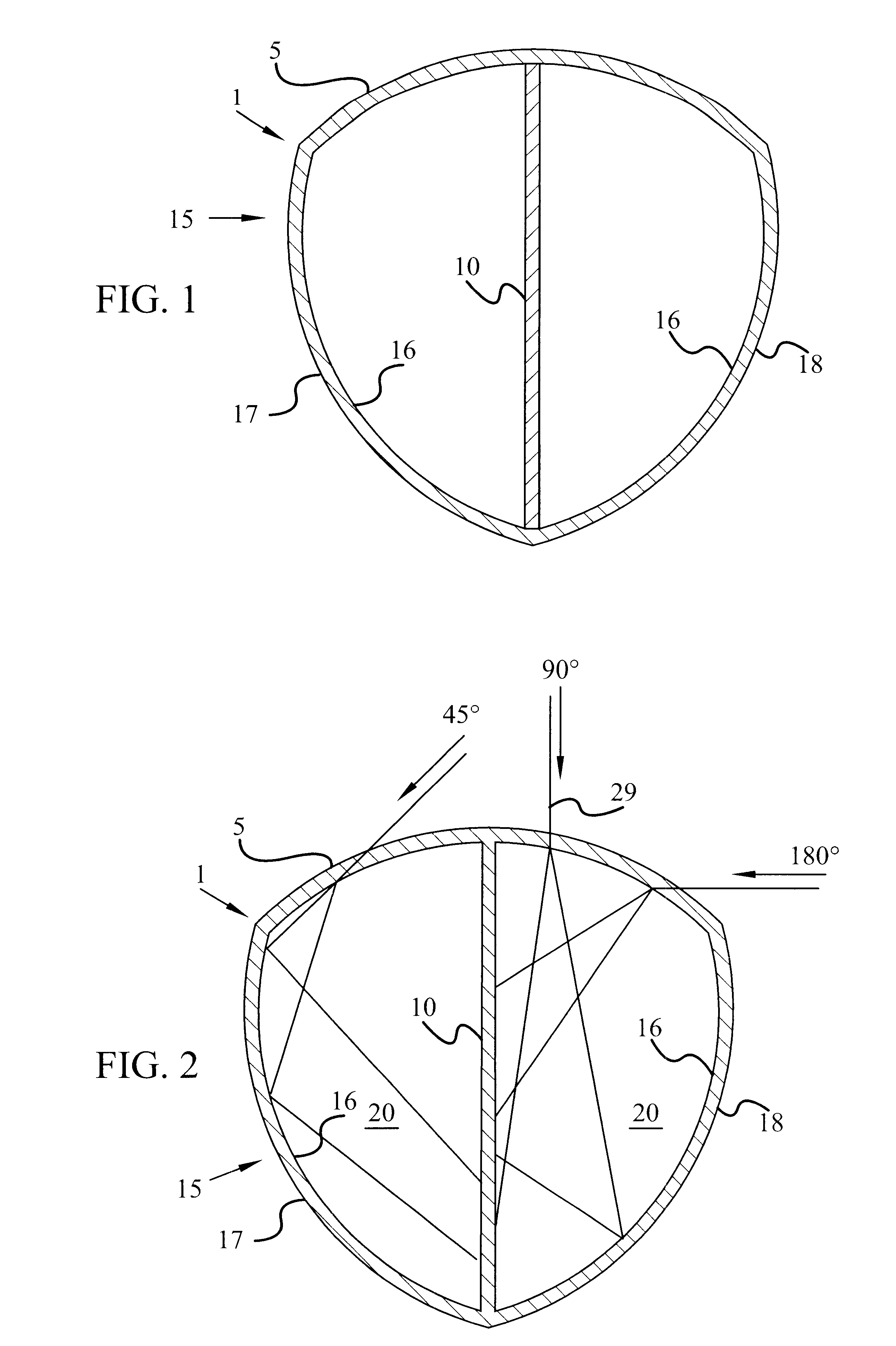
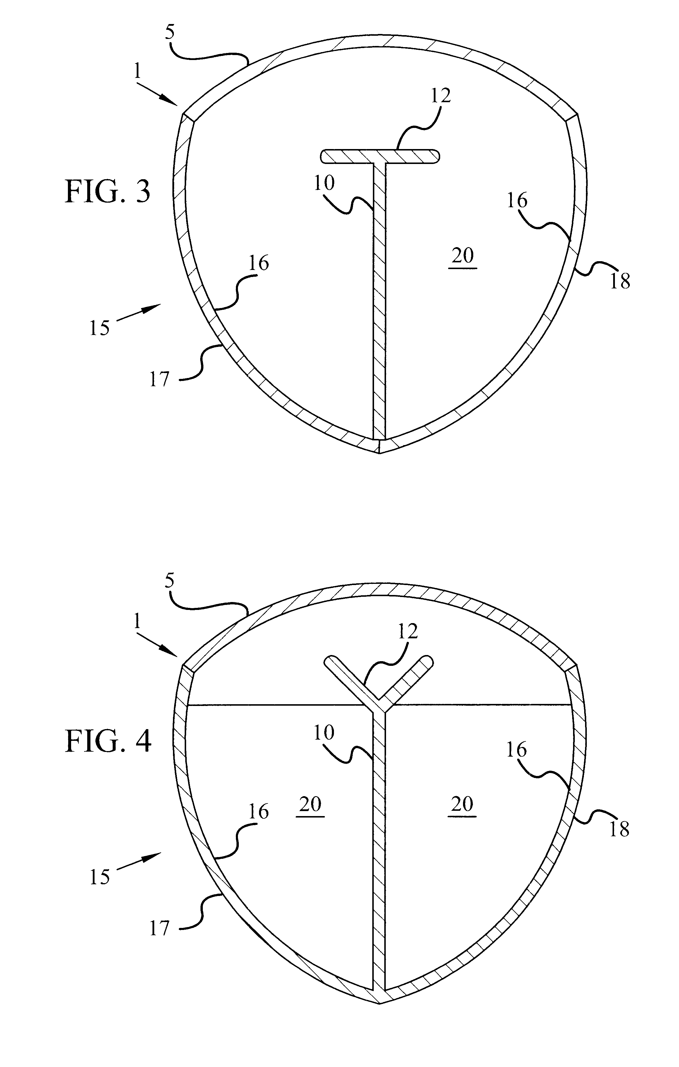
Although the present invention may be readily adapted to a variety of embodiments of a solar collector pipe, with reference to FIGS. 1-4, solar collector pipe 1 is an example of a solar collector pipe of the invention. It will be understood by one of ordinary skill in the art that the invention is not limited to the specific structures illustrated in the drawings.

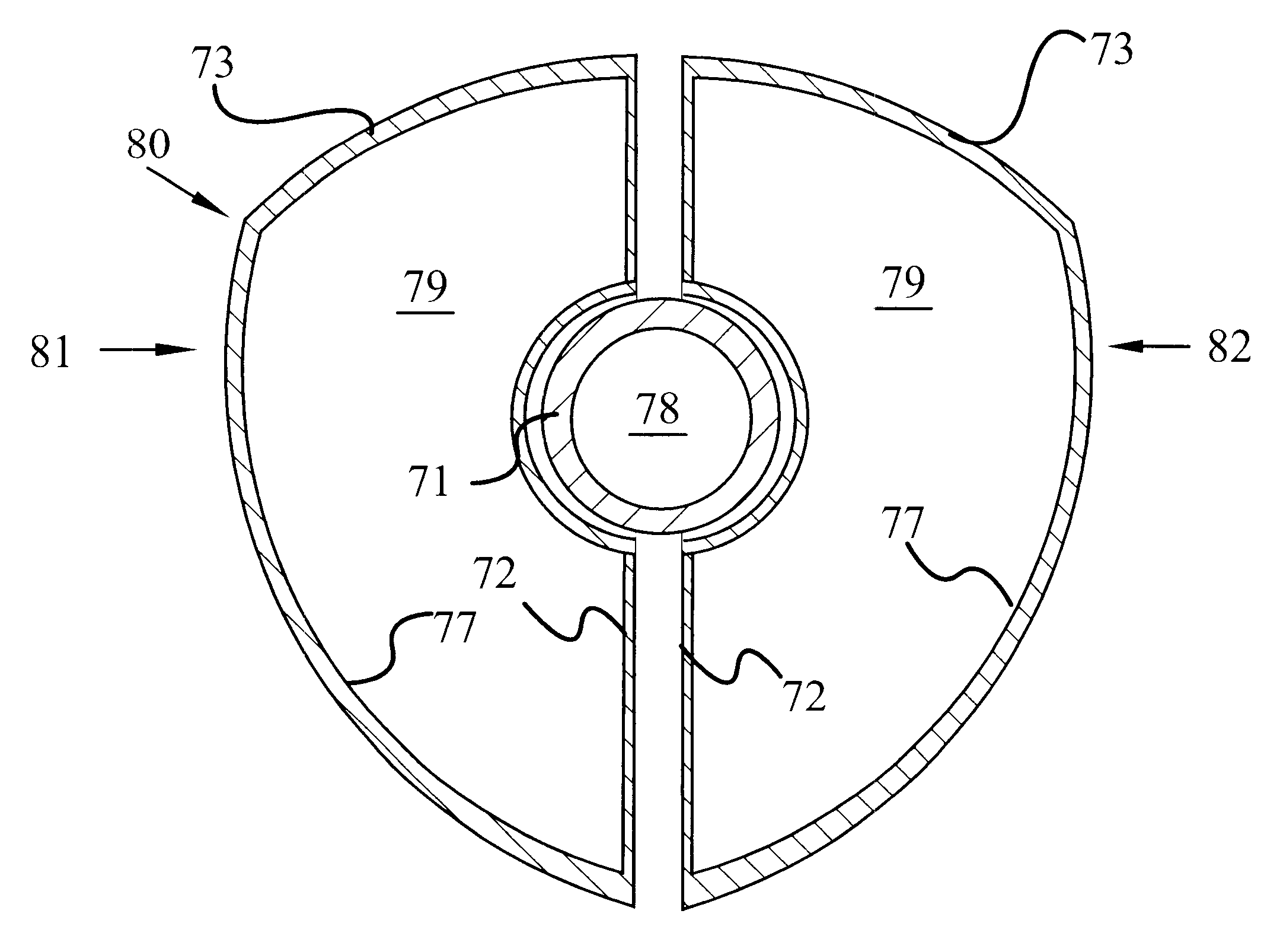
Solar collector pipe 1 directly conveys internal fluid 20 to be heated and collects and transfers solar energy efficiently and directly to fluid 20, thereby maximizing both the amount of energy transmitted to fluid 20 and the peak temperature attainable by fluid 20. Solar collector pipe 1 includes transparent portion 5 for admitting solar energy into solar collector pipe 1. Absorbing portion 10 for absorbing solar energy is internal to solar collector pipe 1. Conduit portion 15 is also included and comprises reflecting surface 16 thereon for reflecting solar energy received through transparent portion 5 onto absorbing porti...


PUM


Abstract

An improved solar collector pipe that directly conveys fluid to be heated and collects and transfers solar energy efficiently and directly to the internal fluid, thereby maximizing both the amount of energy transmitted to the internal fluid and the peak temperature attainable by that fluid. The solar collector pipe includes a transparent portion for admitting solar energy into the solar collector pipe. Internal to the solar collector pipe is an absorbing portion for absorbing solar energy. A conduit portion is also included and comprises a reflecting surface thereon for reflecting solar energy received through the transparent portion onto the absorbing portion. In embodiments of the invention, the transparent portion, the conduit portion, and the absorbing portion together define at least one fluid passageway for conveying the fluid. In other embodiments of the invention, an internal conduit defines a fluid passageway for conveying the fluid. The internal conduit may be supported within the solar collector pipe and supported by heat-absorbing portions, or may be placed between two solar collector pipe sections to form a single solar collector pipe with an internal conduit extending therethrough.

Description

BACKGROUND OF INVENTION1. Technical FieldThis invention relates to the field of solar energy collection, and more specifically, to a solar collector pipe.2. Background ArtWith the increasing cost of conventional fuel and energy for heating and cooling, much attention has been directed to the possibility of the use of sunlight as a source of energy for heating. Assorted solar water heating systems have previously been provided. For example, some conventional solar water heating systems involve a box which uses a transparent glass plate as a top surface of the box. Inside the box, a plurality of round black PVC pipes are placed in a snake-like pattern, back and forth through the box. Other conventional solar water heating systems involve a water-containing, round, black tube heated by solar radiation in the center of a space defined by a solar energy collector.Both of these types of conventional solar water heating systems are placed in a location exposed to the sun, such as on the ro...

Claims


Application Information

Patent Timeline
Patent Type & Authority Patents(United States)
IPC IPC(8): F24J2/46F24J2/04F24J2/10F24J2/05F24J2/52F24J2/24F24J2/06F24J2/26F24J2/00F24S10/40F24S10/55F24S10/70F24S10/75F24S20/30F24S23/70F24S23/71
CPCF24J2/0488F24J2/05F24J2/1047F24J2/245F24J2/26F24J2/4647F24J2/5203F24J2/541F24J2002/467Y02E10/44Y02E10/47F24S10/40F24S10/742F24S10/75F24S23/80F24S25/30F24S30/425F24S70/60F24S80/30F24S2025/6007
Inventor GHELA, MANU
Owner GHELA MANU
Why Eureka
Try Eureka