
Squeeze film damping type bearing

a damping type and squeeze film technology, applied in the direction of bearings, shafts, ball bearings, etc., can solve the problems of complex mounting, vibration damping of bearings, and vibration exposure of bearings

Inactive Publication Date: 2003-09-30
TECHSPACE AERO
View PDF12 Cites 10 Cited by
  • Summary
  • Abstract
  • Description
  • Claims
  • Application Information

AI Technical Summary

Benefits of technology

The present invention aims to provide a solution which prevents any free rotation of the seals, especially at the base, but which still allows said seals to achieve a precessional motion relative to it.
The present invention aims also to propose an alternative solution, wherein no space for installing centring rods is required, and for which the assembling of the various pieces is easy to perform.

Problems solved by technology

In this particular case, an additional problem comes from the fact that this type of bearing has to be provided with a centring system which has to take over this axial force.
The main problem is therefore double: it lies in the leaktightness of such a classical device and in the centring of said device relatively to the axial force.
The bearings are subjected to vibrations brought about by certain imbalances.
The presence of oil maintained under pressure in the annular space, by means of the orbital motion, has the effect of creating a damping of the vibration.
They are thus expensive.
Furthermore, they are intricate to mount.
Finally, they have an uncalibrated oil leakage and thus their damping is not always fully controlled.
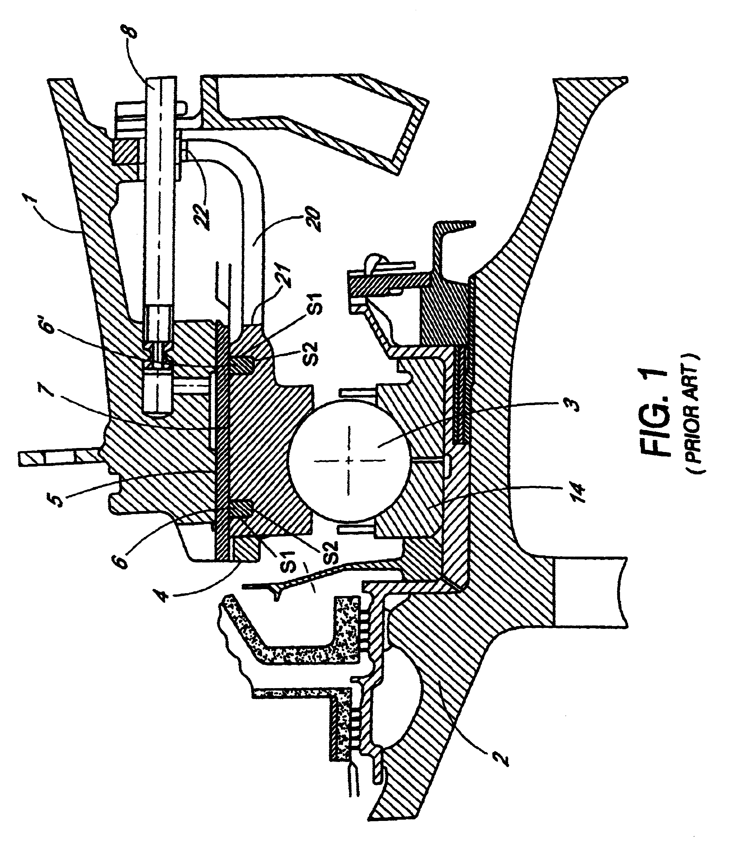
Furthermore, this arrangement requires a certain space for installing the oil damper, especially for installing the centring rods about the motor axis.
Therefore, this arrangement remains inappropriate for small turning devices.
In addition, the assembling of this type of structure is relatively complex.

Method used


Image

  • Squeeze film damping type bearing
  • Squeeze film damping type bearing
  • Squeeze film damping type bearing

Examples


Embodiment Construction

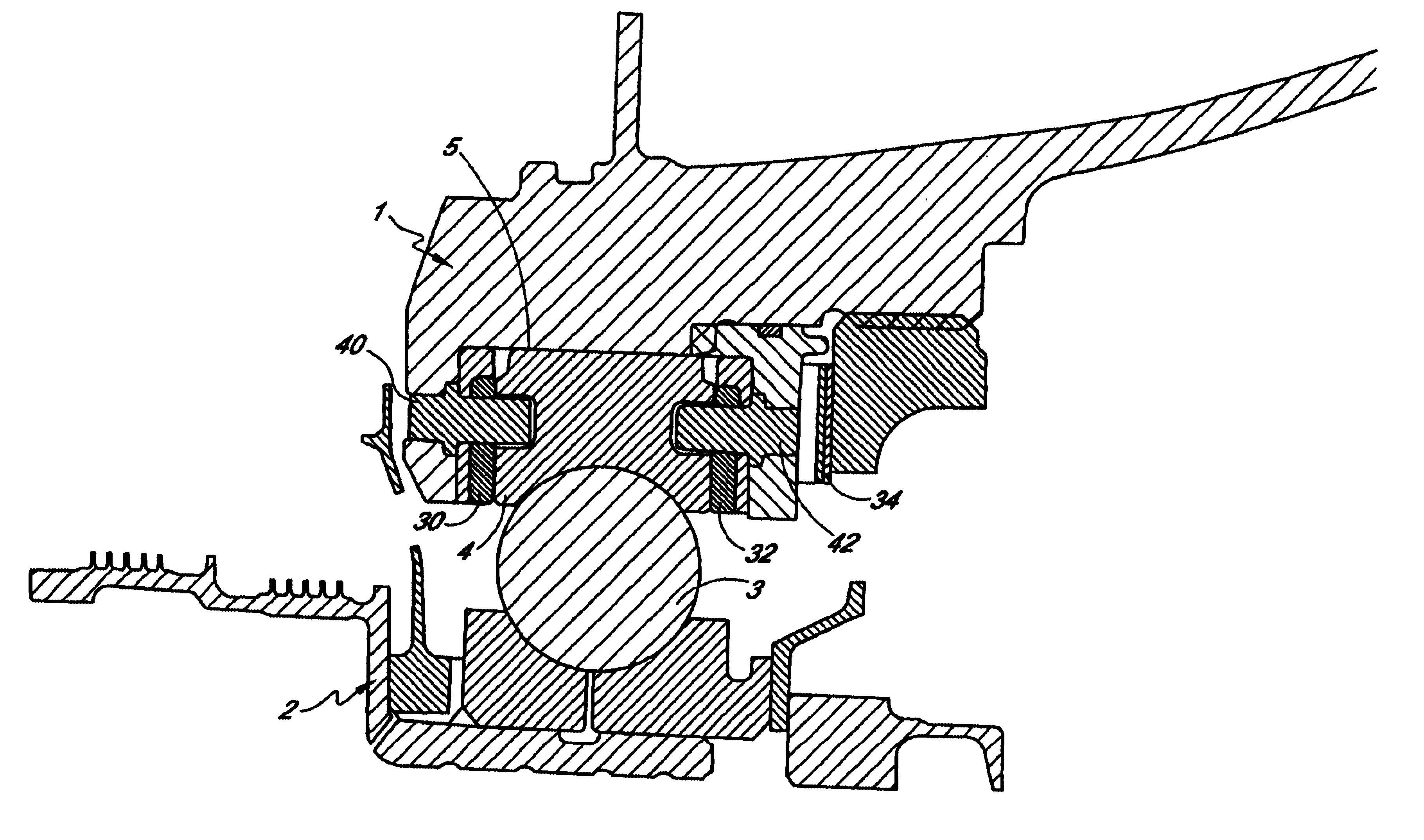
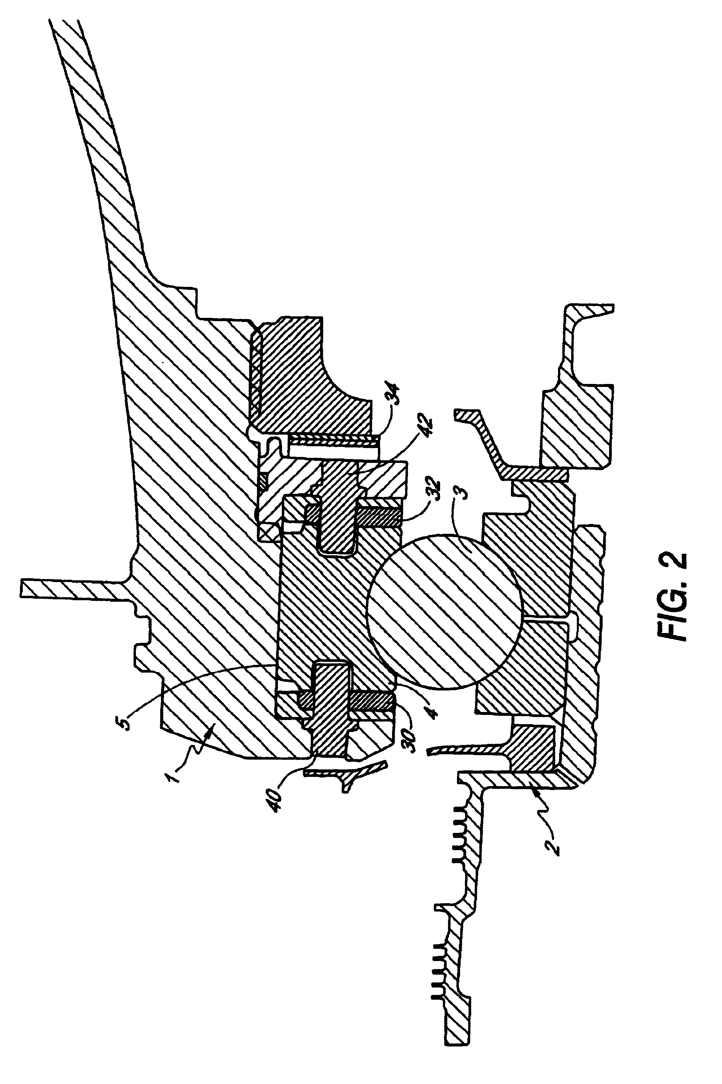
The present invention aims to solve the problem of the satisfactory sealing of the oil film of the damper or "squeeze film" and the axial retention in the case of a thrust bearing.

This is solved, surprisingly, by proposing to arrange two sides seals 30 and 32 in an annular form along the two sides surfaces of the outer rolling race 4. These are therefore substantially two circular plates between which said outer rolling race 4 is gripped.

According to one preferred embodiment, these seals are made of carbon, since carbon has advantageous self-lubricating properties.

According to another embodiment, these seals may be made of an elastomeric material, optionally combined with a part made of carbon.

The gripping is achieved with the aid of a series of anti-rotation fixing members which pass through the said side seals 30 and 32 and securely fasten them to the two circular side surfaces of the outer rolling race 4. Although rotation is prevented by the presence of such anti-rotation member...


PUM


Abstract

The present invention is related to a bearing for maintaining an inner mobile structural component with a revolution symmetry, rotating inside an outer structural component, which is itself fixed or mobile, said bearing comprising a set of balls or rollers and at least an outer race which provides the mechanical contact between said balls or rollers and said outer structural component, said bearing also comprising a pressurized-oil damper known as a "squeeze film" damper, arranged at the annular contact surface between said outer race and the outer structural component, characterized in that each side surface of the outer race is in contact with a side seal having an annular form, said seals being securely fastened to the outer race by means of a series of anti-rotation fixing members.

Description

This application claims priority to European Application Serial Number 00 870 149.2, filed Jun. 30, 2000, the disclosure of which is incorporated herein by reference in its entirety.1. Field of the InventionThe present invention relates to a damping device of "squeeze film" type which acts as a pressurized-oil damper, integrated in a rolling bearing, which is intended in particular to be used in civil aeronautics.Specifically, the invention relates to the rolling bearing using the damping device.2. Description of Related ArtA rolling bearing such as, for example, in an aircraft engine, serves as a link between one or more inner mobile members, preferably having a revolution symmetry and rotating about an axis, and an outer structural component. The outer structural component may itself be either fixed or mobile. This structure also has a revolution symmetry relative to the rotational axis of the mobile member(s). It may be, for example, in the shape of a cone.The rolling bearing con...

Claims


Application Information

Patent Timeline
IPC IPC(8): F16C27/04F16C27/00
CPCF16C27/045F16C19/06F16C33/581F16C2360/23
Inventor BOS, MATHIEURYHON, SEBASTIEN
Owner TECHSPACE AERO
Learn More