Method of and a system for measuring a stress or a stress distribution, using a stress luminescent material

a luminescent material and stress technology, applied in the direction of force measurement, force measurement, force measurement by measuring optical property variation, etc., can solve the problems of large amount of labor required to complete an operation, inability to measure a stress distribution on a small object, and the possibility of obtaining measured data

Inactive Publication Date: 2003-09-30
NAT INST OF ADVANCED IND SCI & TECH
View PDF5 Cites 14 Cited by
  • Summary
  • Abstract
  • Description
  • Claims
  • Application Information

AI Technical Summary

Benefits of technology

The tested body may be formed by a bulk body prepared by mixing a powder of the stress luminescent material with a transparent material, or a film obtained by at first mixing the powder of the stress luminescent material with the transparent material and then applying the mixed materials to the surface of a measurement object. However, the above-mentioned correlation can be used in both of the two cases, i.e., with one case using the bulk body as a tested body, and the other case using the above film to form a tested body, thereby obtaining similar effects.
The present invention has been accomplished in accordance with the above newly found knowledge, and its object is to solve the problems existing in the above-described conventional stress measuring methods. Namely, it is an object of the present invention to provide a method and a system which, by making use of a stress luminescent material, renders it possible to directly observe a stress distribution on the base of a real time without using a cord, and to easily measure a stress or a stress distribution and a stress image.
The luminous intensity of the stress luminescent material of the tested body may be effectively detected by using a peak value of an emission spectrum obtained through a spectroscope. Alternatively, it is effective that the luminous intensity of the stress luminescent material is detected while at the same time illuminating the tested body using an illumination light having a wave length which is different from the peak value of the emission spectrum. Of course, this can also be done by adding a filter in front of the photodetector, the filter of which can only pass the light with the wavelength of the stress luminescent material.
The measurement of a stress or a stress distribution over a tested body may be carried out by a measurement system including a photodetector for detecting the luminous intensity of the stress luminescent material of the tested body; a computing means capable of comparing a detected value from the photodetector with certain correlation data indicating a relationship between the luminous intensity of the stress luminescent material and a stress, and then computing a stress on the tested body; a display device capable of displaying the tested body's received stress which has been computed by the computing means. Therefore, it is possible to efficiently and correctly measure and record the stress or the stress distribution over the tested body.
Furthermore, the luminous intensity of the stress luminescent material of the tested body may be detected only by using a peak value of an emission spectrum obtained through a spectrometer. Alternatively, the luminous intensity of the stress luminescent material may be detected while at the same time illuminating the tested body using an illumination light having a wavelength which is different from the peak value of the emission spectrum. In this way, it is possible to remove an undesired influence from the surrounding lights and to improve a measurement precision. Of course, this can also be done by adding a filter in front of the photodetector, the filter of which can only pass the light with the wavelength of the stress luminescent material.

Problems solved by technology

However, this method only makes it possible to obtain measured data of a portion where a strain gauge has been attached.
As a result, a large amount of labour is needed to complete an operation for attaching a great number strain gauges to a great number of measuring points on an object.
Moreover, if an object to be measured is relatively small, attachment of strain gauges will be difficult, making it impossible to measure a stress distribution on a small object.
Consequently, it is impossible to perform a stress measurement in a actual operation or a stress measurement in-situ and in real time.
However, none of any methods described in the above can be used to easily measure a stress distribution under a condition where the tested body is still being used.

Method used


Image

  • Method of and a system for measuring a stress or a stress distribution, using a stress luminescent material
  • Method of and a system for measuring a stress or a stress distribution, using a stress luminescent material
  • Method of and a system for measuring a stress or a stress distribution, using a stress luminescent material

Examples


example 1

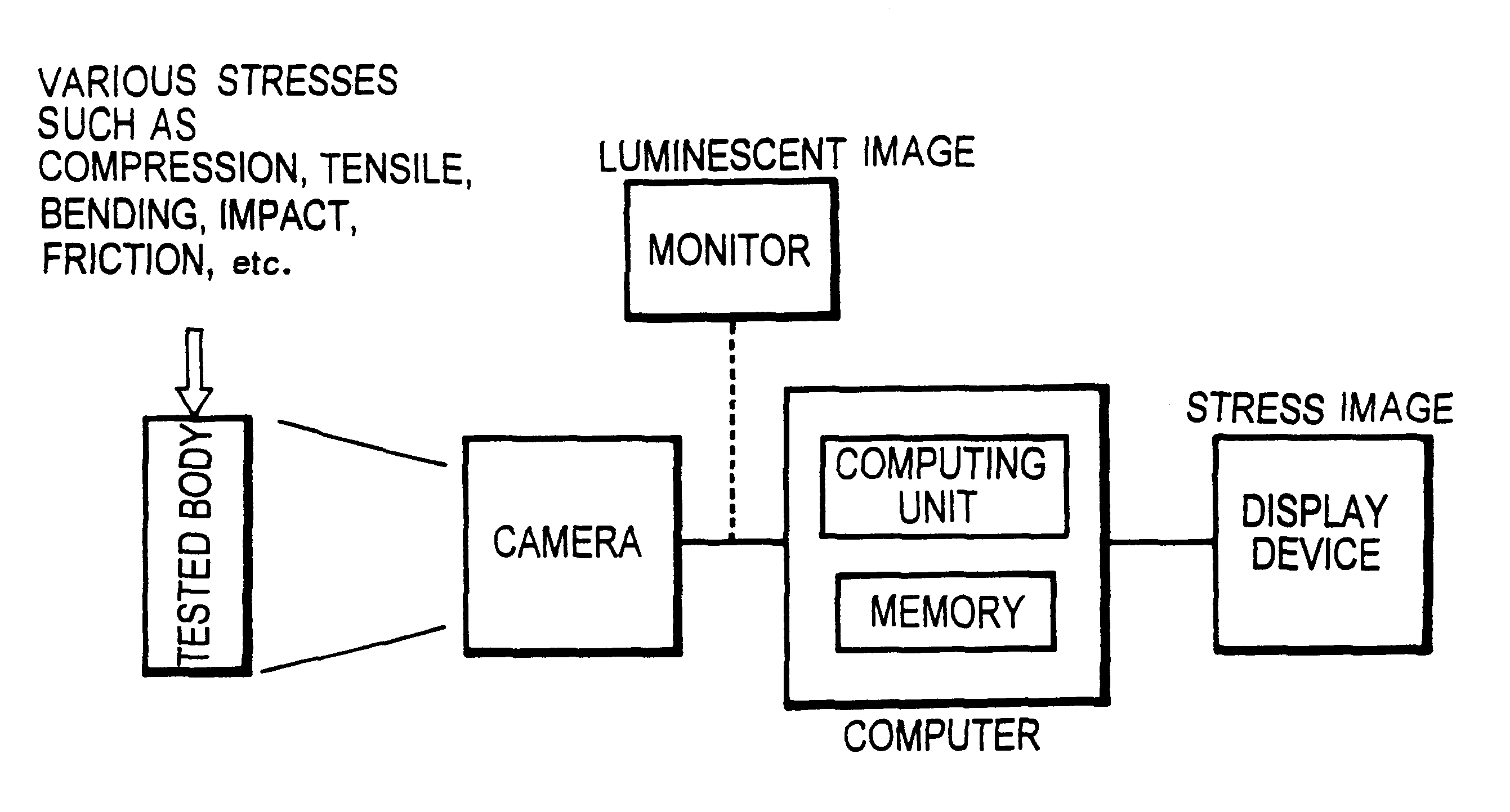
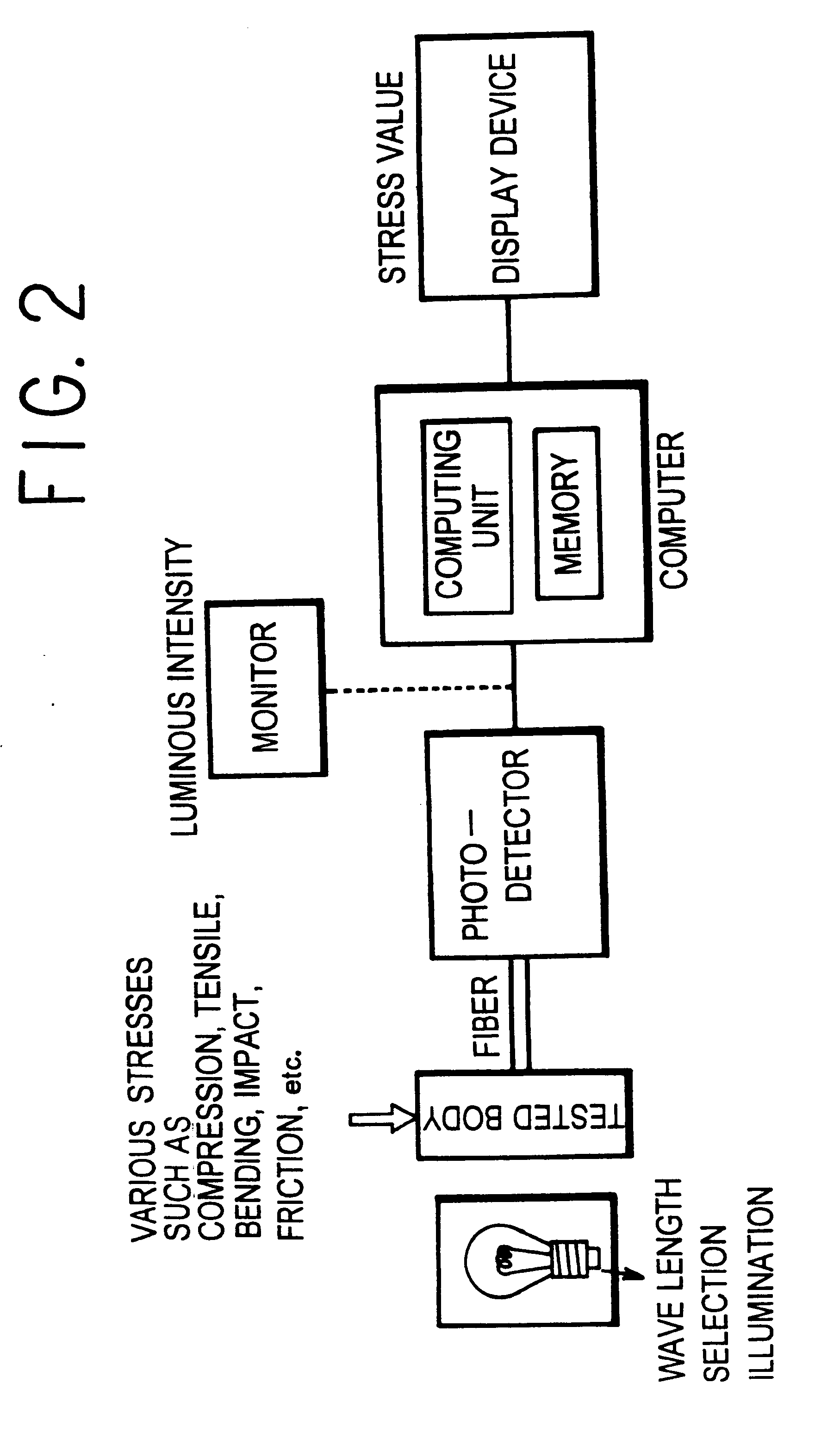
This is an example using a measuring system shown in FIG. 2 to analyze a local stress when a tested body is a bulk body.

At first, a tested body was prepared in the following process. Namely, various necessary components were taken by weighing the weights thereof, in a manner such that a defect-controlled type SAO-E stress luminescent material may be formed by strontium carbonate, europium oxide and alumina and has a composition of Sr.sub.0.985 Al.sub.2 O.sub.4 :Eu.sub.0.01. Then, the above components were mixed together and burned in an air atmosphere at a temperature of 800.degree. C. for 60 minutes, followed by a further burning treatment in a reductive atmosphere (5% H.sub.2 / Ar) at a temperature of 1300.degree. C. for 4 hours. Afterwards, the burned material was ground, thereby obtaining a powder material which was a stress luminescent material.

Subsequently, the powder material obtained in the above process was mixed with an optical resin in accordance with a weight ratio of 50 ...

example 2

This is an example of analyzing a stress image using a measuring system shown in FIG. 3.

The tested body S4 was subjected to a bending test, and a stress picture was measured on the base of a real time. As a result, it was understood that using a stress luminescent material makes it possible to monitor a mobile stress distribution in a real time.

It is understood from the above facts that the measuring method of the present invention, as compared with a conventional method, makes it possible to extremely easily and continuously obtain a stress image with a high sensitivity.

FIGS. 9A to 9C and FIGS. 10A and 10E are used to illustrate examples of analyzing stress distribution images, indicating a compression stress and a tensile stress exerting on the tested bodies S5 and S6.

The stress distributions calculated from the stress luminescent images have been proved to be coincident with the results analyzed by using Finite Element Method or strain gauge method. Thus, it is understood from th...

example 3

This is an example of analyzing a stress exerting on an object which is coated with a stress luminescent film.

A stress luminescent material SAO-E powder was mixed at a weight ratio of 90 wt % with a transparent resin, so as to obtain a paste. The obtained paste was then applied to the surface of a measurement object to form a paste layer having a thickness of 0.01 mm. Subsequently, the object was hardened at a temperature from a room temperature to 80.degree. C., thereby obtaining results similar to those obtained in the case where a bulk body is used as a tested body.

Furthermore, it was understood that a stress distribution image can be obtained, in a manner similar to the case where the bulk body is used as a tested body.

Then, a system shown in FIG. 4 was used to measure an emission spectrum at this time. Meanwhile, an illumination having a wave length different from the peak value of the emission spectrum was used as an illumination to irradiate the tested body. As a result, it w...


PUM

PropertyMeasurementUnit
wavelengthaaaaaaaaaa
temperatureaaaaaaaaaa

Abstract

This invention is to provide a method and a system which, by making use of a stress luminescent material, renders it possible to directly observe a stress distribution on the base of a real time without electrical contacts, and to easily measure a stress or a stress distribution and a stress image. Essentially, the invention comprises the steps of adding a stress to a tested body containing a stress luminescent material whose light emission is proportional to the stress, making visually observable a stress distribution over the tested body in accordance with a luminous intensity of the stress luminescent material contained in the tested body, measuring the luminous intensity of the luminescent material of the tested body, comparing the measured value of the luminous intensity with certain correlation data indicating a relationship between the luminous intensity of the stress luminescent material and a stress, thereby obtaining a stress value or a stress distribution over the tested body.

Description

The present invention relates to a method of and a system for measuring a stress or a stress distribution, using a stress luminescent material, which method is capable of easily measuring or monitoring a stress value, a stress distribution and a stress image on a measurement object such as a tested body, without physical contacts.DESCRIPTION OF THE RELATED ARTMeasuring the magnitude of various kinds of stress occurring in different parts of an object has been considered to be extremely important in every aspect of people's daily life, especially in the field of designing a machine or a physical facility.For this reason, there have been developed various different methods for measuring a stress distribution. Among them, a typical and most generally used method requires that an electric resistance strain gauge be attached to an object to carry out a predetermined stress measurement. However, this method only makes it possible to obtain measured data of a portion where a strain gauge h...

Claims


Application Information

Patent Timeline
Patent Type & Authority Patents(United States)
IPC IPC(8): G01L1/24G01L1/00
CPCG01L1/24
Inventor XU, CHAO-NANAKIYAMA, MORITONONAKA, KAZUHIROWATANABE, TADAHIKO
Owner NAT INST OF ADVANCED IND SCI & TECH
Why Eureka
Try Eureka