Driving apparatus, power output apparatus, and control method

a technology of power output apparatus and driving apparatus, which is applied in the direction of motor/generator/converter stopper, dynamo-electric gear control, dynamo-electric converter control, etc., can solve the problem of limited driving efficiency of electric motors

Inactive Publication Date: 2003-10-07
TOYOTA CENT RES & DEV LAB INC +1
View PDF15 Cites 70 Cited by
  • Summary
  • Abstract
  • Description
  • Claims
  • Application Information

AI Technical Summary

Problems solved by technology

However, driving efficiency of the electric motor is limited when the range of the input voltage is limited.

Method used


Image

  • Driving apparatus, power output apparatus, and control method
  • Driving apparatus, power output apparatus, and control method
  • Driving apparatus, power output apparatus, and control method

Examples


Embodiment Construction

Concrete examples of the control of the present embodiment will be described below. First, however, to illustrate the effect of current decrease of the present invention the relationship between motor outputs and phase currents will be shown using simulated values.

The simulation was performed using the following procedure. First, a phase current iu1 of one phase (here upon u-phase) is divided into an average value (direct-current component) idc per one rotation and the other components (alternating-current components) iac. Moreover, as for the alternating-current components iac, a function g(.theta.) normalized by their amplitudes Iac is introduced.

That is: ##EQU1##

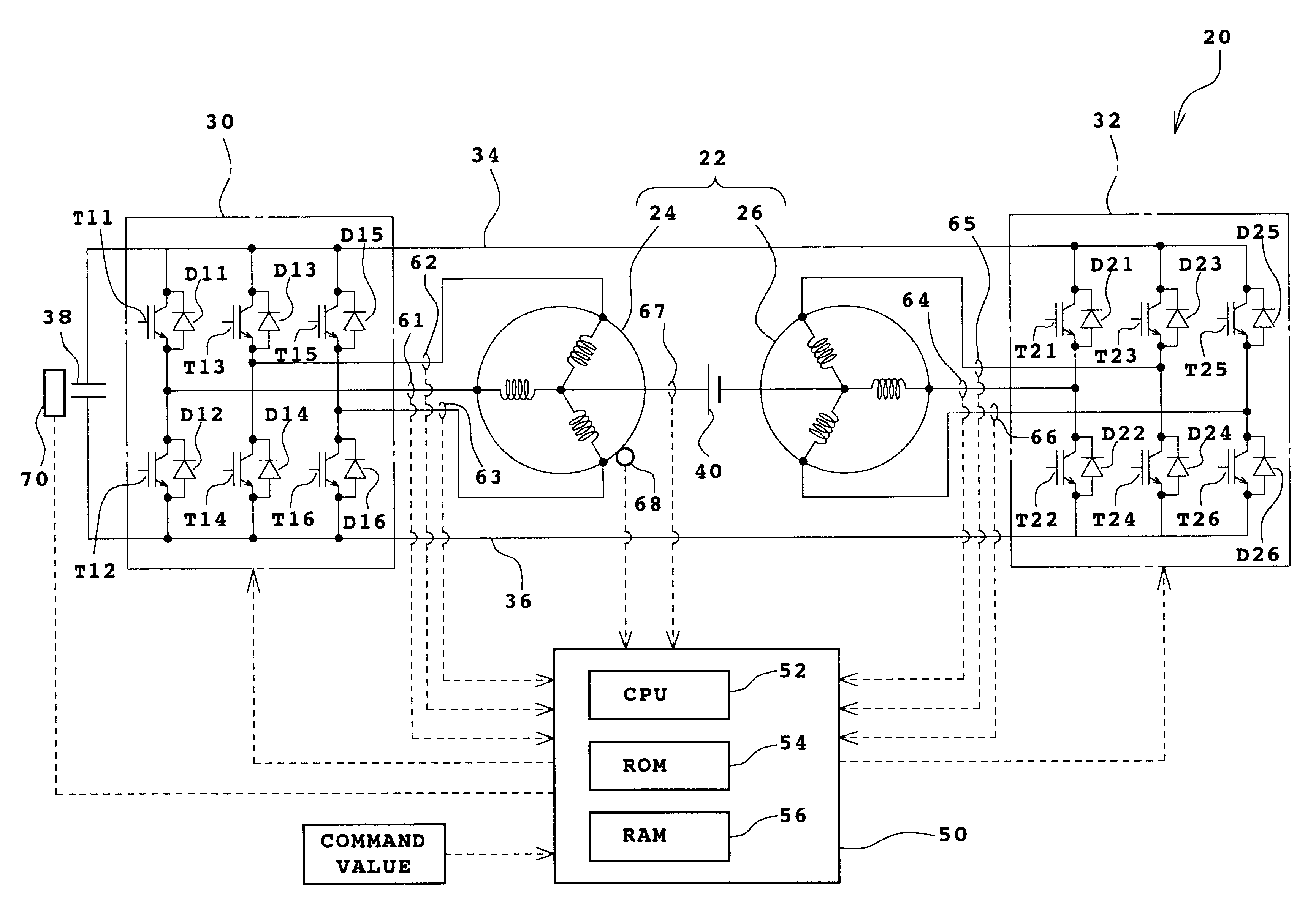
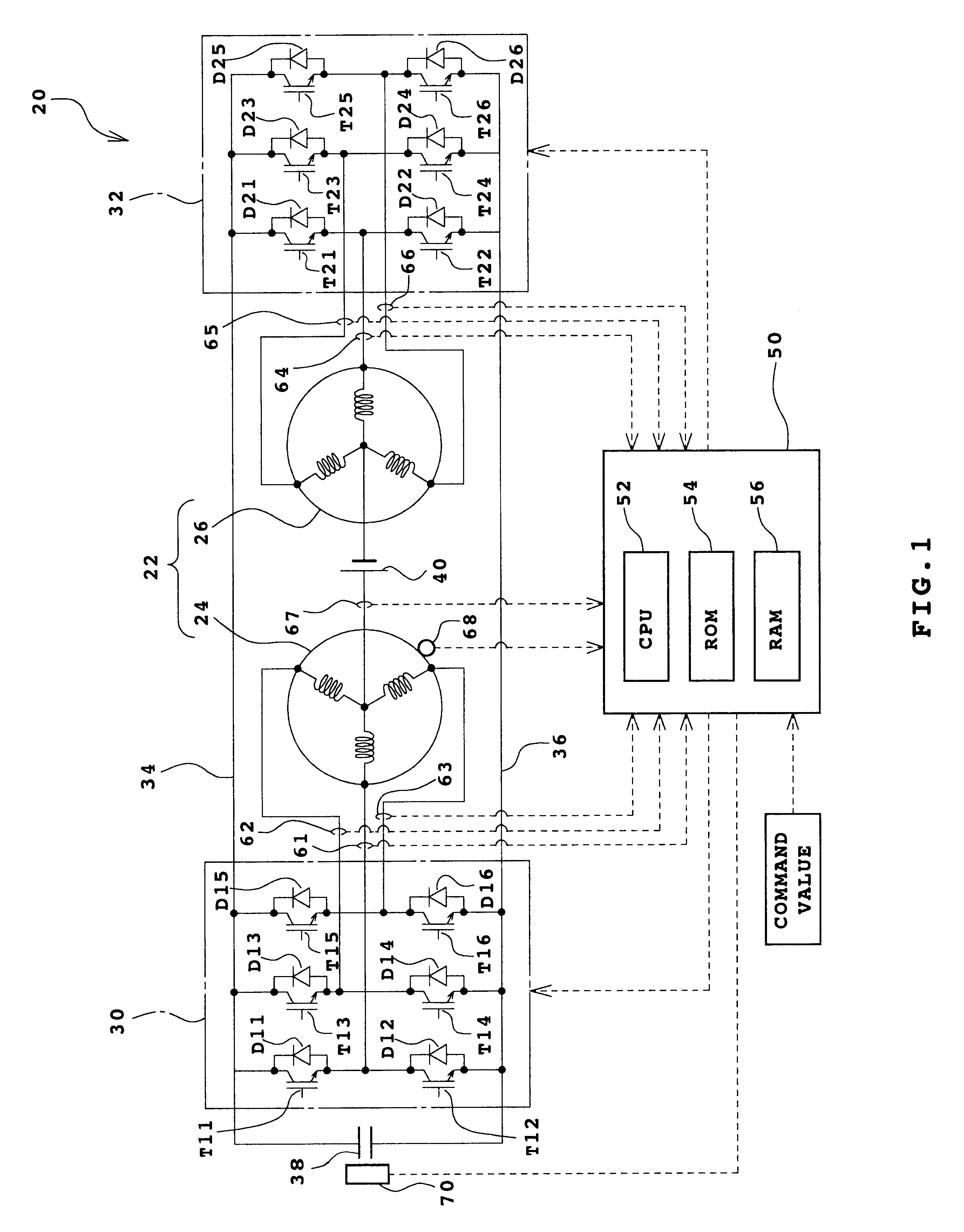
Successively, a voltage Vw is defined on the basis of the relation between the battery voltage E and the capacitor voltage Vc of the present system. This is done because, for the amplitude Iac of the phase current, the voltage obtained by the subtraction of the battery voltage E from the capacitor voltage Vc assumes the m...


PUM


Abstract

A direct-current power supply (40) is connected between the neutral points of two three-phase coils (24, 26) of a 2Y motor (22) constituted of the windings of the two three-phase coils (24, 26), which are connected in Y-connection and wound on a same stator, and to which three-phase alternating current power is severally supplied with a phase difference of a shifted angle between the windings from two inverter circuits (30, 32) having a positive pole bus (34) and a negative pole bus (36) for common use. A capacitor (38) is connected between the positive pole bus (34) and the negative pole bus (36). The electric potential difference between the neutral points of the three-phase coils (24, 26) is made larger or smaller than the voltage of the direct-current power supply (40) through the switching control of the inverter circuits (30, 32). Thereby, the capacitor (38) can be charged or discharged. Consequently, an inverter input voltage can be adjusted within a wide range.

Description

1. Field of the InventionThe present invention relates to a driving apparatus, a power output apparatus, and to a control method applicable to these apparatuses.2. Description of the Related ArtA power output apparatus provided with a capacitor connected between a positive pole bus and a negative pole bus of an inverter circuit for applying a three-phase alternating current to an electric motor and a direct-current power supply connected between the positive pole bus or the negative pole bus of the inverter circuit and a neutral point of an electric motor has been proposed in, for example, Japanese Laid-Open Patent Publications No. Hei 10-337047 and Hei 11-178114. All these publications require that the apparatus have the functions of charging the capacitor and driving the electric motor by realizing, by time shearing, the operation of making a circuit composed of coils in each phase of the electric motor and switching devices of the inverter circuit function as a booster chopper ci...

Claims


Application Information

Patent Timeline
Patent Type & Authority Patents(United States)
IPC IPC(8): H02P6/00H02P6/08H02M7/5387H02P1/24H02P5/74H02P21/00H02P21/22H02P25/022H02P27/06H02P27/08
CPCH02P6/08H02P6/005H02P6/10
Inventor MORIYA, KAZUNARIINAGUMA, YUKIONAKAI, HIDEOOHTANI, HIROKISHAMOTO, SUMIKAZUKOMATSU, MASAYUKISASAKI, SHOICHI
Owner TOYOTA CENT RES & DEV LAB INC
Why Eureka
Try Eureka