
Machining assembly including a rotating tool and exhaust hood

a technology of rotating tools and exhaust hoods, which is applied in the direction of maintenance and safety accessories, milling equipments, sawing apparatuses, etc., can solve the problems of obstructing chip removal, reducing the useful life of cutting tools, and marring the surface of machined workpieces

Inactive Publication Date: 2003-11-04
LEDERMANN
View PDF3 Cites 8 Cited by
  • Summary
  • Abstract
  • Description
  • Claims
  • Application Information

AI Technical Summary

Benefits of technology

In accordance with one preferred embodiment of the present invention the exhaust hood can be adapted variable to the diameter of the disk-shaped section of the cutting tool so that the width of the gap between the disk-shaped section of the cutting tool and the inner edge of the exhaust hood remains a minimum. This is achievable, for example, via an annular insert adapted to the inner diameter of the exhaust hood at the outer diameter of the disk-shaped section of the tool. By minimizing the gap between the cutting tool and the exhaust hood an unnecessarily high exhaust capacity of the exhaust hood is avoided in thus achieving reduced operating costs.
Preferably, the exhaust opening in the cowled exhaust hood, via which air and chips are removed from the cowled exhaust hood, is arranged staggered by 20.degree. to 150.degree. in the direction of motion of the tool cutter relative to the chip production site, an arrangement being particularly preferred in which the exhaust hood is arranged staggered by 90.degree. in the direction of motion of the tool cutter relative to the chip production site. This permits assuring that, in addition to the natural motion of the chip in the axial direction, the motion of the chip in the radial direction generated by the centrifugal forces is made use of for chip removal. The air exhaust through the opening in the cowled exhaust hood is thus able to optimally support and boost the natural direction of motion of the chip in thus permitting effective chip removal.

Problems solved by technology

Experience has shown such an exhaust to be inadequate, however, resulting in chips partly being cat multiply which reduces the useful life of the cutting tools, or leaves the machined workpiece surface marred.
Known furthermore are the problems involved with cemented materials, often resulting in a conglomerate of cement and chips which may lead to clumping greatly obstructing chip removal as a whole.

Method used


Image

  • Machining assembly including a rotating tool and exhaust hood
  • Machining assembly including a rotating tool and exhaust hood
  • Machining assembly including a rotating tool and exhaust hood

Examples


Embodiment Construction

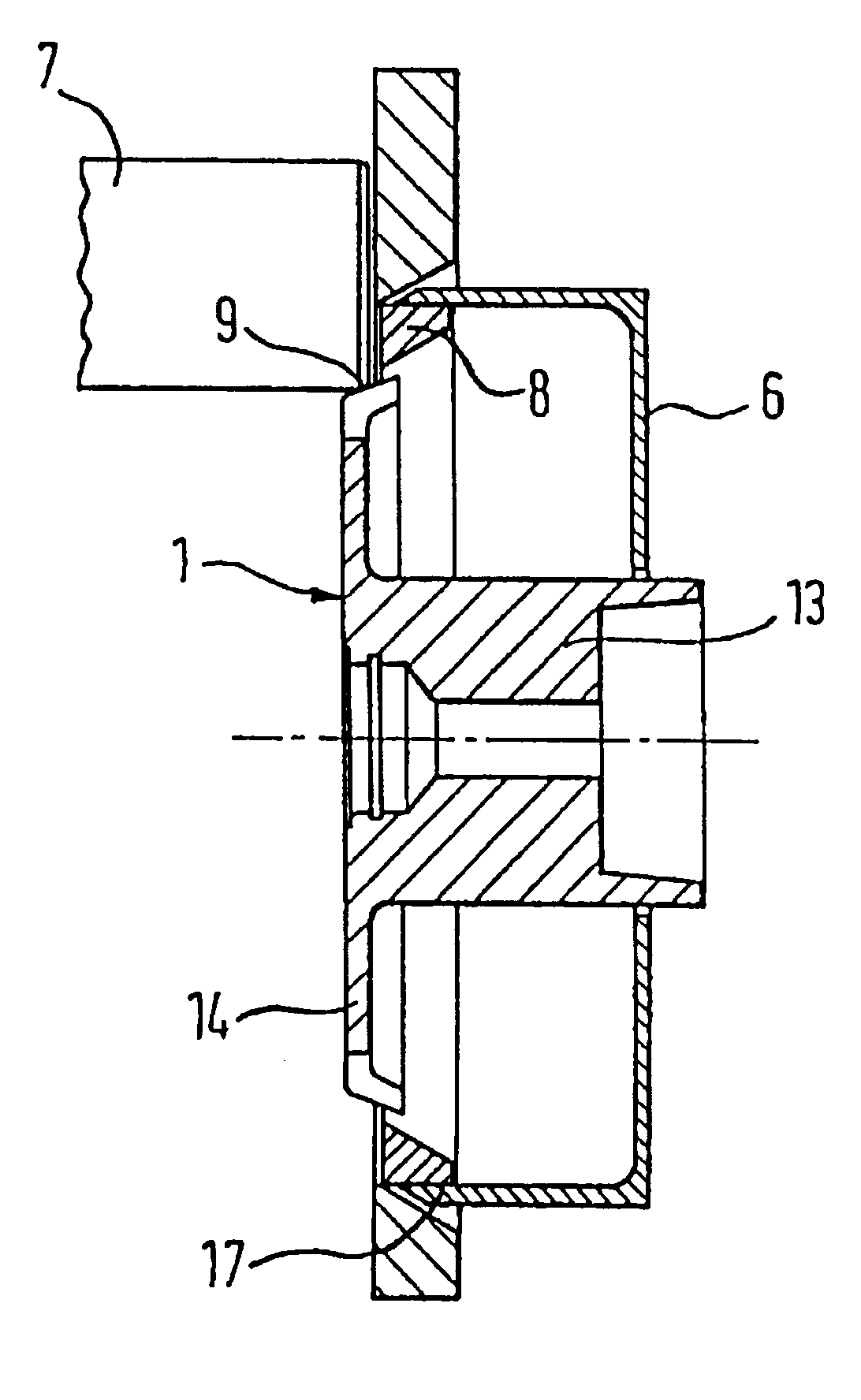
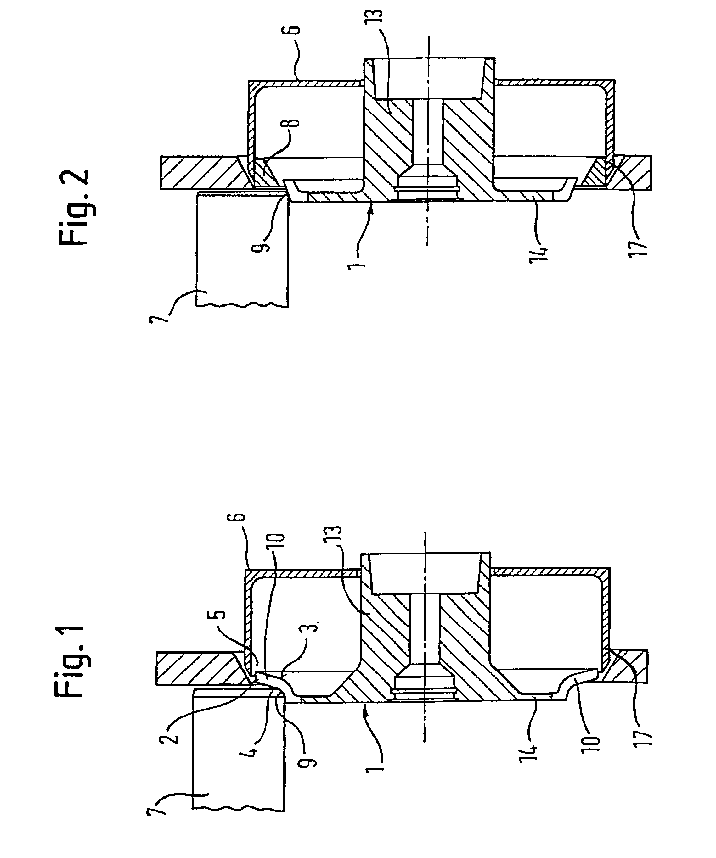
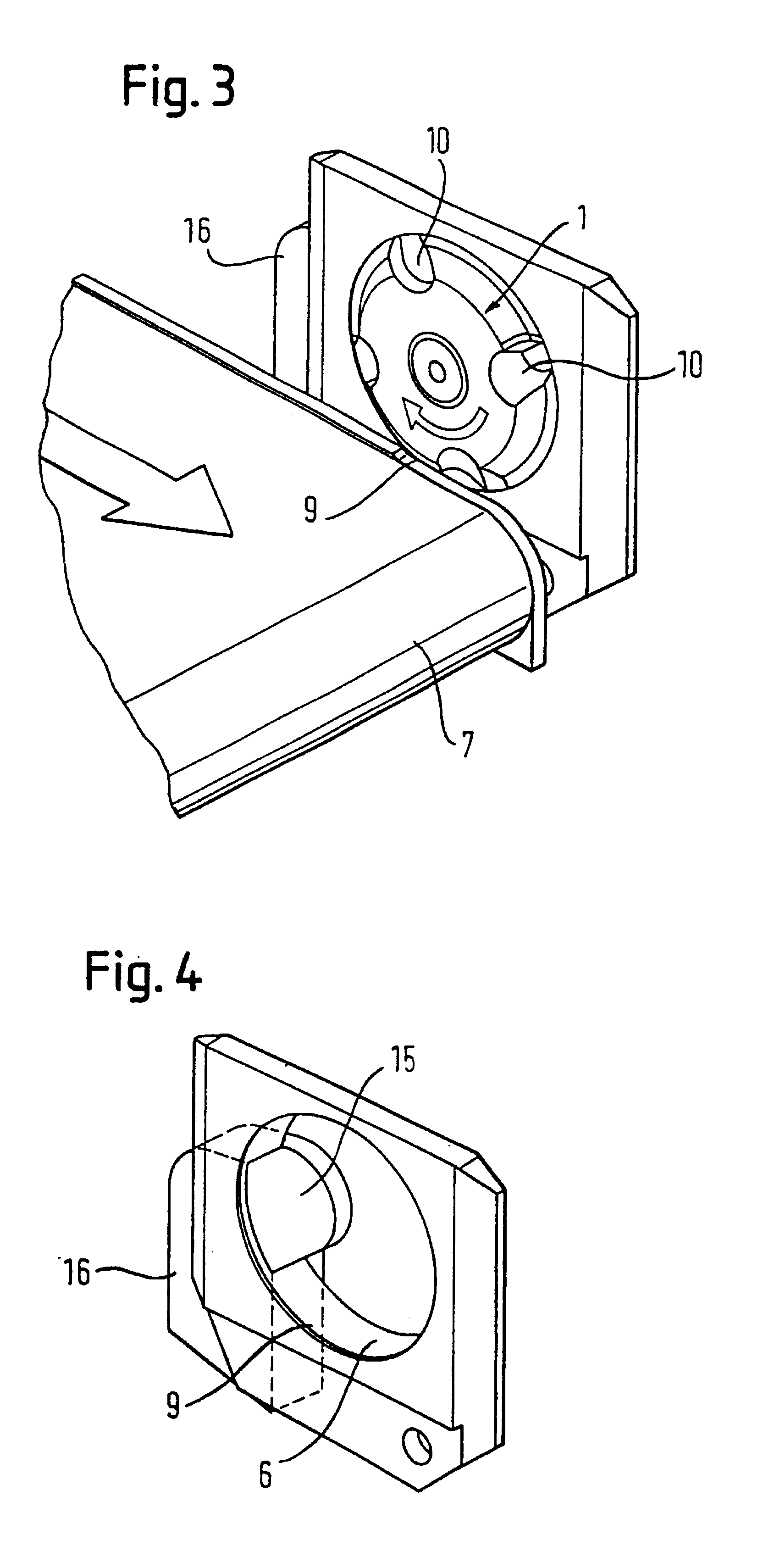
Referring now to FIG. 1 there is illustrated diagrammatically a first embodiment of the invention. The cutting tool 1 is formed substantially by a cylindrical connector 13 for receiving the spindle of a machine tool (not shown) as well as a substantially disk-shaped section 14 connected thereto. Arranged in the radial outer portion of the disk-shaped section 14 are several cutters 4 in the circumferential portion of the cutting tool 1. The spindle-side inner contour 3 of the tool 1 matches the contour of the cutter 4, resulting in a quill at the side facing the tool spindle. FIG. 1 shows the tool 1 cutting a workpiece 7 to be machined.

Positioned coaxially with the cutting tool 1 is an exhaust hood 6 which encircles the portion of the disk-shaped section 14 adjoining the workpiece 7 as well as of the cylindrical connector 13. In this arrangement, the exhaust hood 6 is fixedly located whilst the cutting tool 1 is rotatably mounted by the spindle of a machine tool (not shown). In the l...


PUM

PropertyMeasurementUnit
inner diameteraaaaaaaaaa
circumferenceaaaaaaaaaa
shapeaaaaaaaaaa

Abstract

The invention relates to a treatment unit with a cutting tool (1) for treating wood, plastic or the like. Said treatment unit comprises a suction hood (6) with a ring (17) that encircles the tool (1) completely in the circumferential direction and at least partially in the axial direction. The suction hood (6) is located on the side of the drive spindle of the tool (1). A chip receiving opening (10) is provided in the tool (1) in the vicinity of the blade (4), said opening traversing the tool (1) in both the axial and the radial direction. A chip formed at the blade (4) is transported through the chip receiving opening (10) to the suction hood (6) from where the chip is removed by air suction.

Description

The present invention relates to a machining assembly including a cutting tool for machining wood, plastics or the like which is connected to an exhaust hood to permit optimum chip removal. More particularly, the present invention relates to a machining assembly as put to use for machining board or panel-type workpieces in a fixed arrangement or on the fly. If the chips fail to be exhausted optimally from such tools the machined surface can be marred by the remaining chips, which is undesirable.PRIOR ARTConventionally, chips resulting from machining wood, plastics or the like such as, for example, wood-replacement or composite materials are exhausted via an exhaust device in the vicinity of the action site between cutter and workpiece. Experience has shown such an exhaust to be inadequate, however, resulting in chips partly being cat multiply which reduces the useful life of the cutting tools, or leaves the machined workpiece surface marred. Known furthermore are the problems involv...

Claims


Application Information

Patent Timeline
Patent Type & Authority Patents(United States)
IPC IPC(8): B23Q11/00B23Q11/08B23C3/12B27D5/00
CPCB23C3/12B23Q11/0046B27D5/006B23Q11/08Y10T409/304088
Inventor KALMBACH, KURTKALMBACH, WILHELMGITTEL, HANS-JURGENWESTFAL, EWALD
Owner LEDERMANN
Learn More