Method and apparatus for atomic force microscopy

a technology of atomic force microscopy and apparatus, applied in the field ofatomic force microscopy, can solve the problems of difficult detection, high resolution optical imaging is therefore difficult to implement in combination with optical levers (or interferometers), near-field scanning optical microscopy,

Inactive Publication Date: 2003-11-04
BRUKER NANO INC
View PDF17 Cites 38 Cited by
  • Summary
  • Abstract
  • Description
  • Claims
  • Application Information

AI Technical Summary

Problems solved by technology

The attractive and repulsive forces between the atoms are very weak, typically about 10.sup.-7 to 10.sup.-12 N, and thus can be difficult to detect.
Although this straight-forward arrangement is useful in some applications, in many applications (for example, near-field scanning optical microscopy, discussed below), the arrangement shown in FIG. 1 has significant disadvantages.
High resolution optical imaging is therefore difficult to implement in combination with the optical lever (or an interferometer) because there is not enough room for both the laser source and / or beam and a high-performance microscope objective.
A similar problem exists with near-field scanning optical microscopy when using a solid immersion lens and a microscope objective.
However, such systems have significant drawbacks including, in the case of the former system, increased noise with attendant poor image quality, and in the latter system, unreliable detection and alignment problems due to an increased path length of the reflected light.
Alternatives to detection using optical beam deflection have been attempted, including using strain gauges and resistive elements disposed on the cantilever, but each has achieved little, if any, practical success due to substantial noise effects that compromise the integrity of the images produced.

Method used


Image

  • Method and apparatus for atomic force microscopy
  • Method and apparatus for atomic force microscopy
  • Method and apparatus for atomic force microscopy

Examples


Embodiment Construction

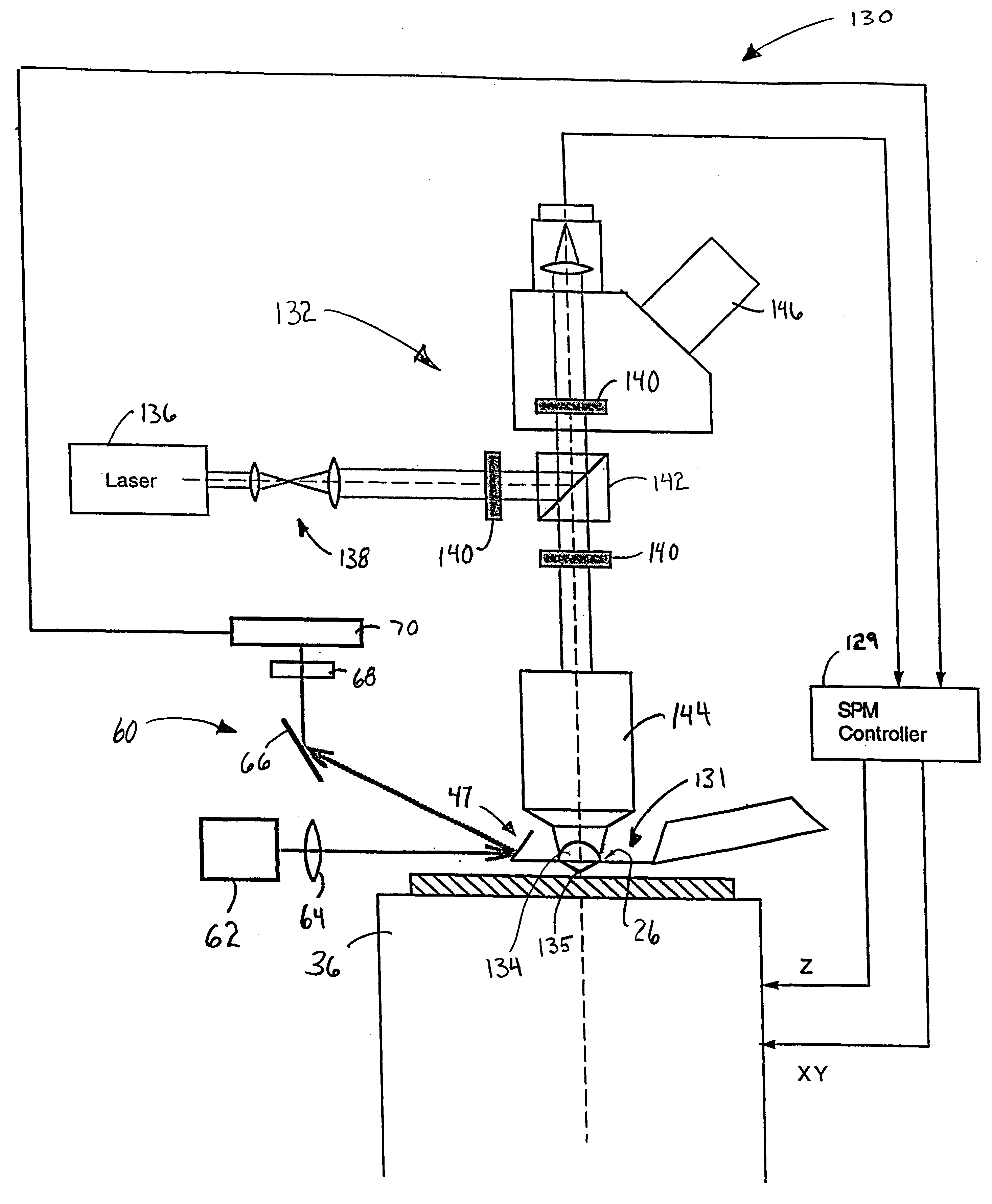
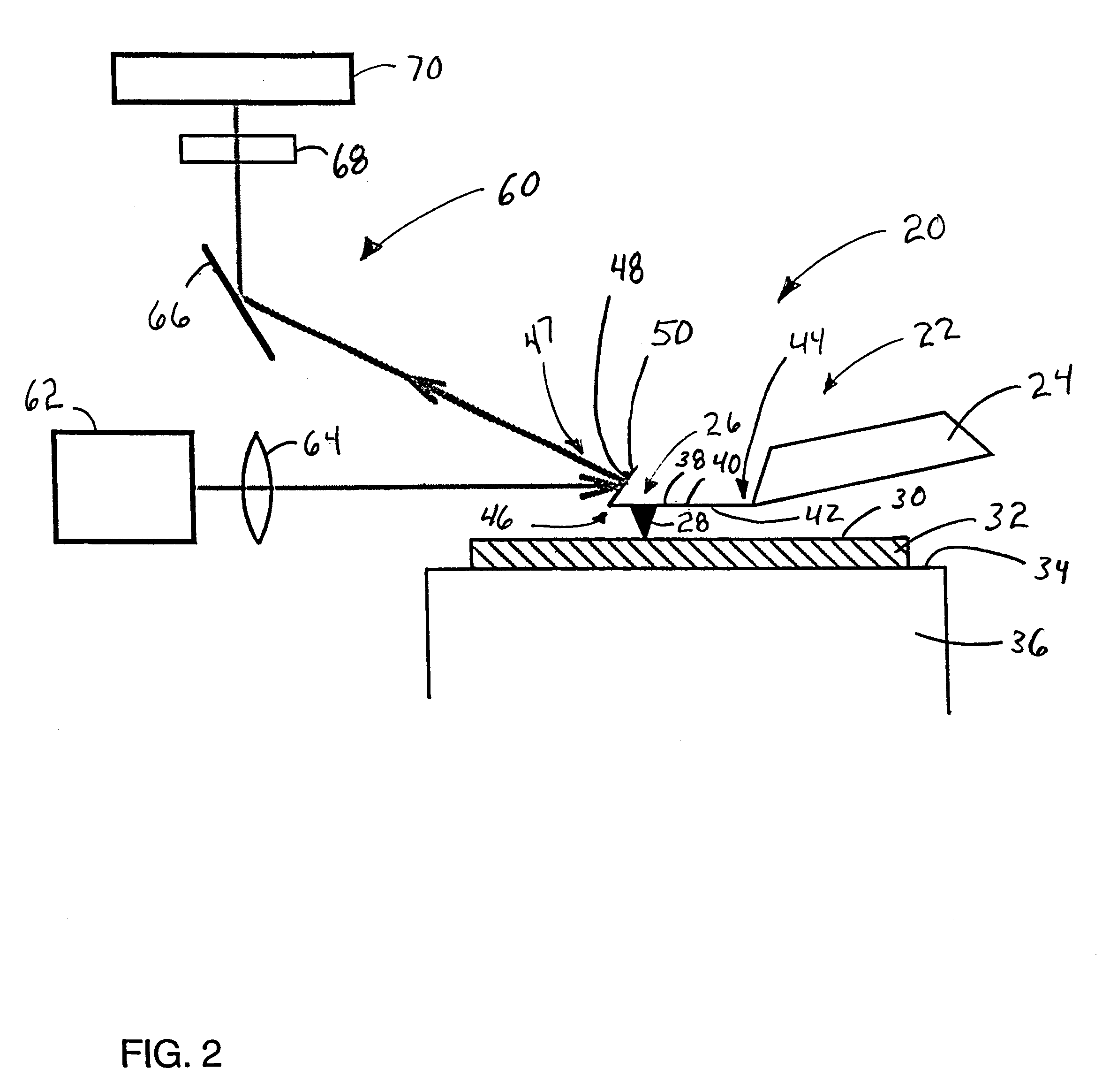
Turning initially to FIG. 2, an AFM 20 of the preferred embodiment includes a probe assembly 22 including a cantilever 26 having a tip 28 extending downwardly therefrom to interact with surface 30 of a sample 32. Sample 32 is placed on a support surface 34 of a scanner 36 which causes movement of sample 32 so as to allow tip 28 to scan surface 30 and image, for example, the topography. Cantilever 26 has a planar body 38 having a top surface 40 and a bottom surface 42, and includes a first, fixed end 44 and a second, free end 46. Fixed end 44 of cantilever 26 is mounted to a substrate 24, while tip 28 is mounted generally adjacent second end 46. Notably, cantilever 26 can be microfabricated so as to have a length on the order of 100 microns, thus facilitating atomic resolution.

Scanner 36 is preferably a piezoelectric tube, but can be a stack of piezo-elements in combination with a mechanical flexure (not shown). Notably, a scanner could be mechanically coupled to substrate 24 to mani...


PUM


Abstract

A method of scanning probe microscopy includes using a cantilever having a planar body, generally opposed first and second ends, and a tip disposed generally adjacent the second end and extending downwardly towards a surface of a sample. Preferably, the sample is disposed on a support surface. The method includes directing a beam of light onto the second end in a direction substantially parallel to the support surface. In operation, the second end directs the beam towards a detector apparatus at a particular angle. Then, the method monitors a change in the angle of deflection of the beam of light caused by deflection of the cantilever as the cantilever tip traverses the surface of the sample, the change being indicative of a characteristic of the surface. Preferably, the second end includes a flat reflective surface, with the flat reflective surface being generally non-planar with respect to the planar body of the cantilever. In addition, the flat reflective surface comprises a mirror fixed to the second end, while in another embodiment, the flat reflective surface is microfabricated integrally with the cantilever.

Description

1. Field of the InventionThe present invention pertains to atomic force microscopy, and specifically, to an apparatus and method for sensing the deflection of a cantilever of an atomic force microscope.2. Description of the Prior ArtAtomic force microscopy is directed to sensing the forces between a sharp stylus or tip of, for example, a probe and the surface of a sample to be investigated. The interatomic forces between the two cause a displacement of the tip mounted on the end of a cantilever, and this displacement is indicative of surface characteristics, e.g., topography, of the sample.An atomic force microscope (AFM) is an apparatus capable of observing these surface characteristics of the sample, which can be on the atomic scale. In one mode of AFM operation, the probe is moved close to the sample surface, and a Van der Waals attractive force acts between an atom at the tip of the probe and an atom on the sample surface. If both atoms move close to each other, so as to nearly ...

Claims


Application Information

Patent Timeline
Patent Type & Authority Patents(United States)
IPC IPC(8): G12B21/00G12B21/08G12B21/02G01Q20/02G01Q60/24G01Q60/38G01Q80/00
CPCB82Y35/00G01Q60/38G01Q20/02Y10S977/87
Inventor GHISLAIN, LUCIEN P.ELINGS, VIRGIL B.
Owner BRUKER NANO INC
Why Eureka
Try Eureka