

Gas turbine set
a technology of gas turbines and sets, which is applied in the direction of liquid fuel engines, machines/engines, efficient propulsion technologies, etc., can solve the problems of consuming comparatively large amounts of steam, requiring a comparatively expensive sealing of the components conducting the cooling steam, and limited cooling air consumption
- Summary
- Abstract
- Description
- Claims
- Application Information
AI Technical Summary
Benefits of technology
Problems solved by technology
Method used
Image

Examples
Embodiment Construction
The present invention has as its object to avoid the disadvantages of the state of the art, in a gas turbine set of the kind named at the beginning.
This is attained by the whole of the features of claim 1.
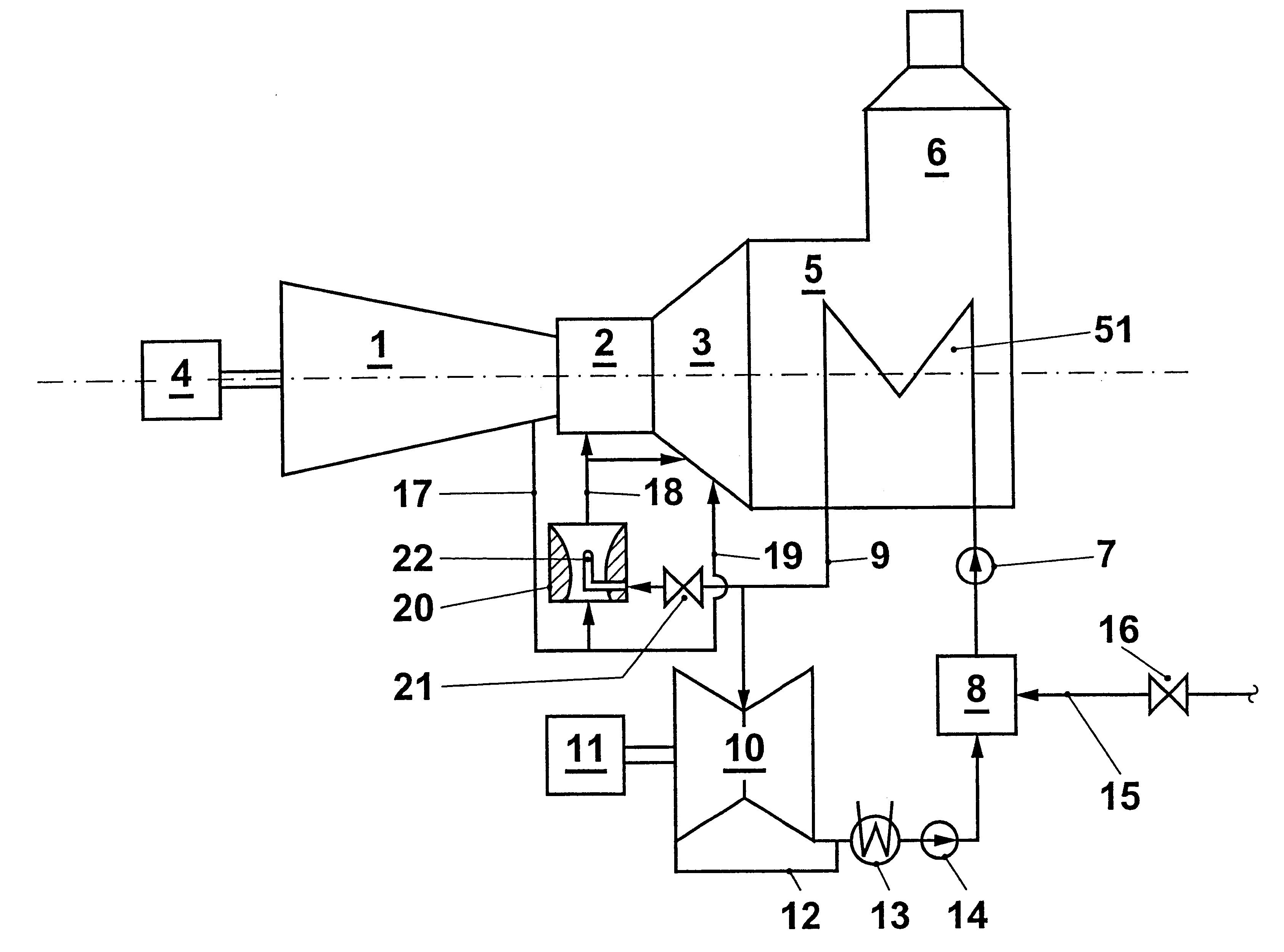
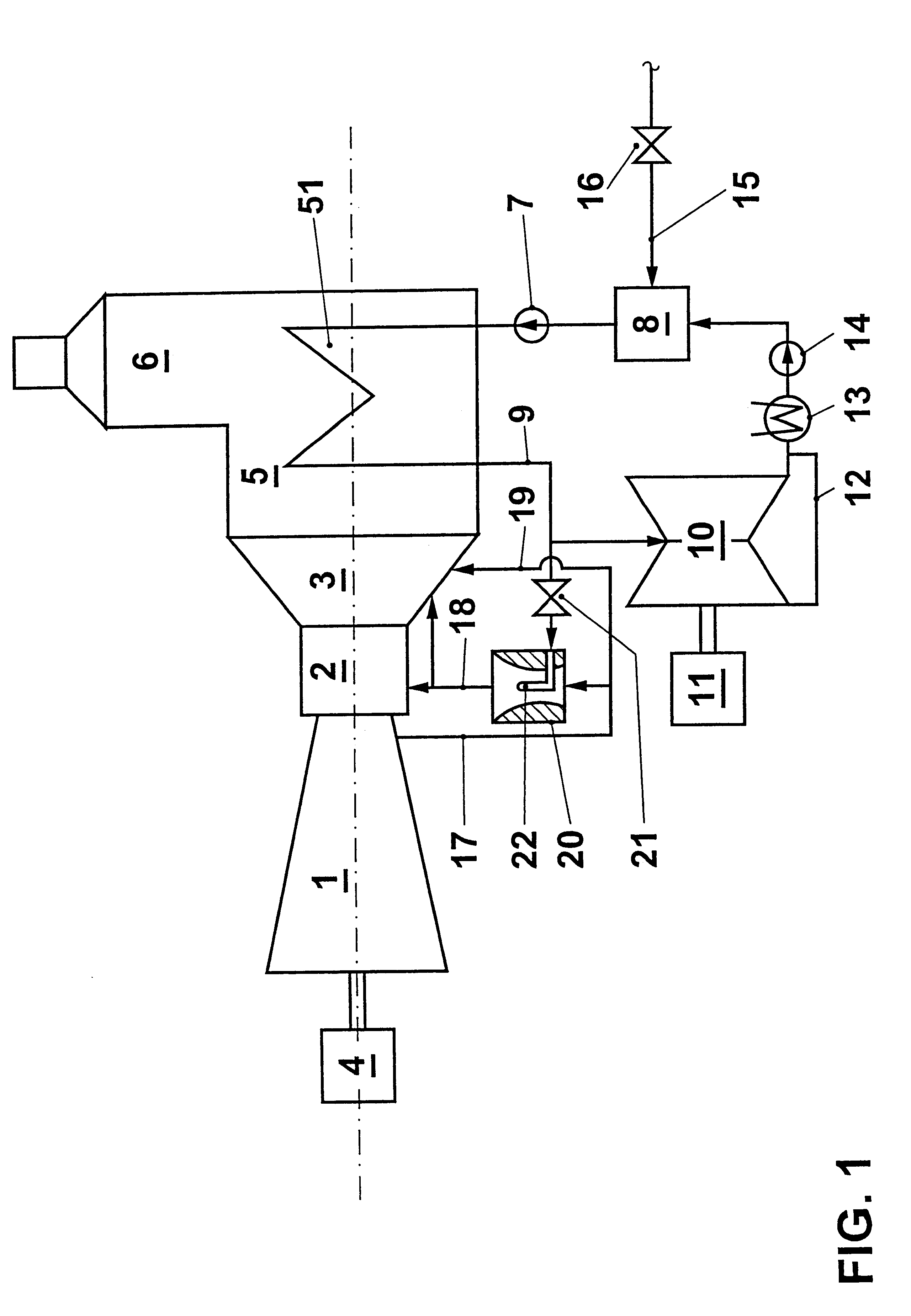
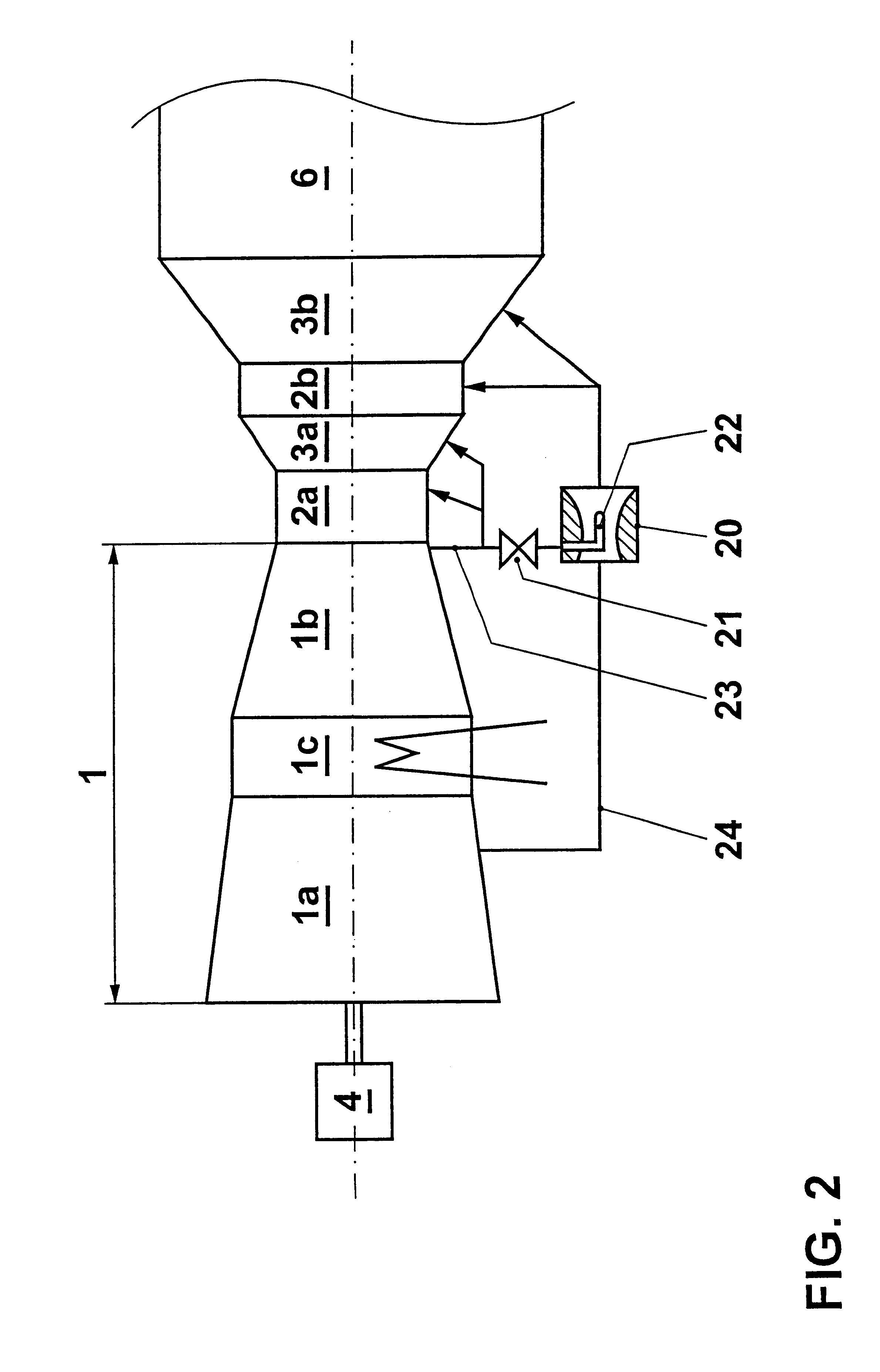
The core of the invention is thus to provide, in an air-cooled gas turbine set, means for increasing the total pressure in the channels which conduct cooling air, and thus to vary the cooling air mass flow at a given cooling air bleed pressure and counter-pressure.
In a preferred embodiment of the invention, ejectors operable with a working fluid are arranged in the cooling air channels.
In this manner, the unavoidable cooling air pressure losses in cooling the combustor and the first rows of turbine blades can be compensated, at least to an important degree. A further concept on which the invention is based is to increase the total initial pressure of the cooling air in strongly throttled cooling air ducts, the film cooling bores also representing throttle points in the proper sense...
PUM
 Abstract
Description
Claims
Application Information