

Oscillator circuit having an improved capacitor discharge circuit
- Summary
- Abstract
- Description
- Claims
- Application Information
AI Technical Summary
Benefits of technology
Problems solved by technology
Method used
Image

Examples
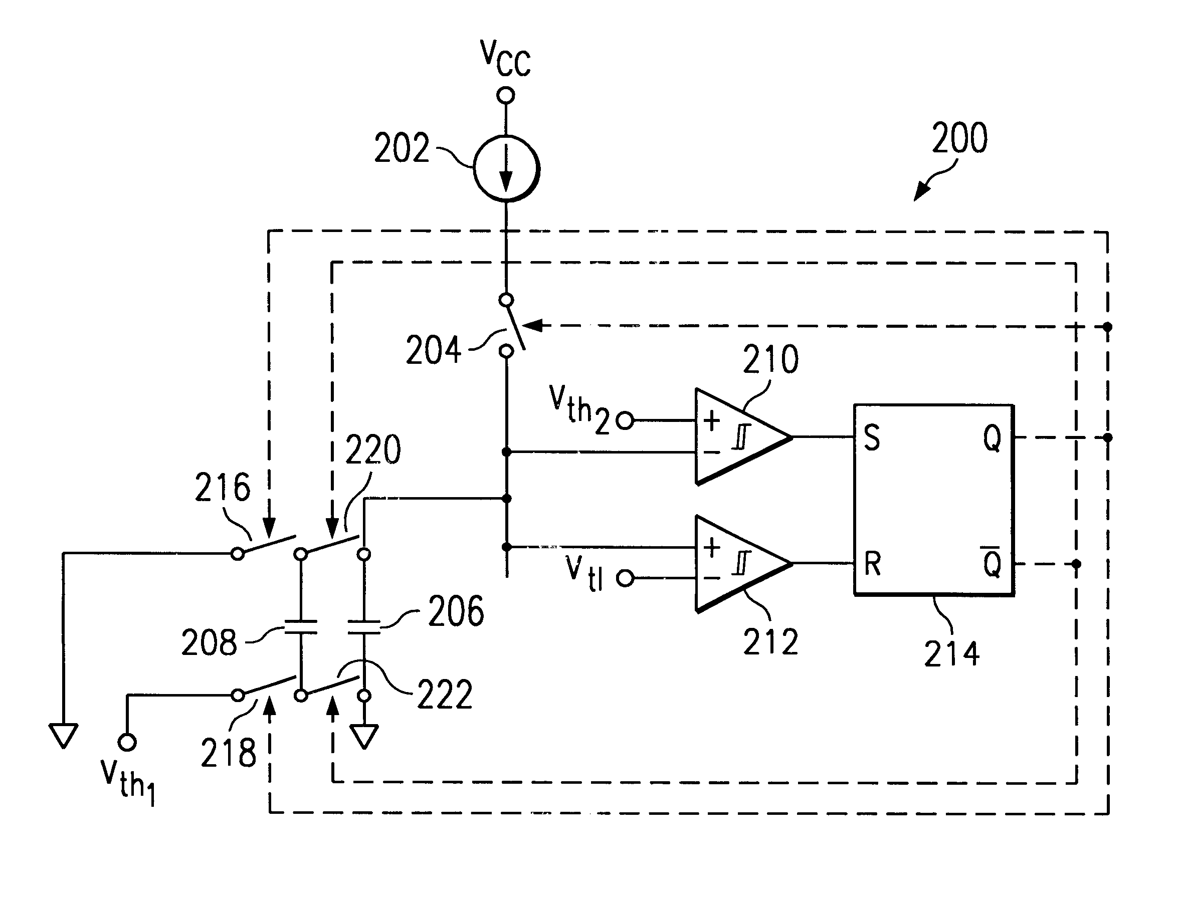
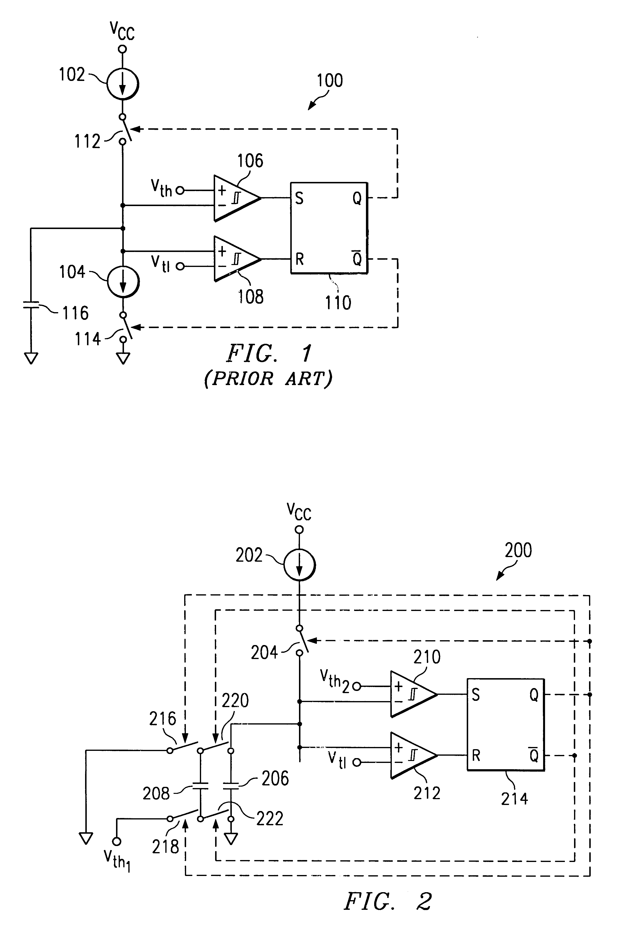
second embodiment
A second embodiment, oscillator 300, as shown in FIG. 3, includes a first capacitor 306, a first charging circuit portion, a first discharging circuit portion, and a first switching network for alternately coupling the first capacitor to the first charging circuit portion and the first discharging circuit portion. The first switching network includes a charging switch network and a discharging switch network. The first charging circuit portion for charging the first capacitor 306 to a high threshold voltage. In addition, oscillator 300 includes a second capacitor 308, a second charging circuit portion and a second switching network for alternately coupling the second capacitor 308 to the second charging circuit portion and ground. The second charging circuit portion for charging the second capacitor 308 to a low threshold voltage V.sub.tL. A set / reset flip-flop 318 enables and disenables the charging cycle and the discharge cycle for the first and second capacitor, 306 and 308. The ...
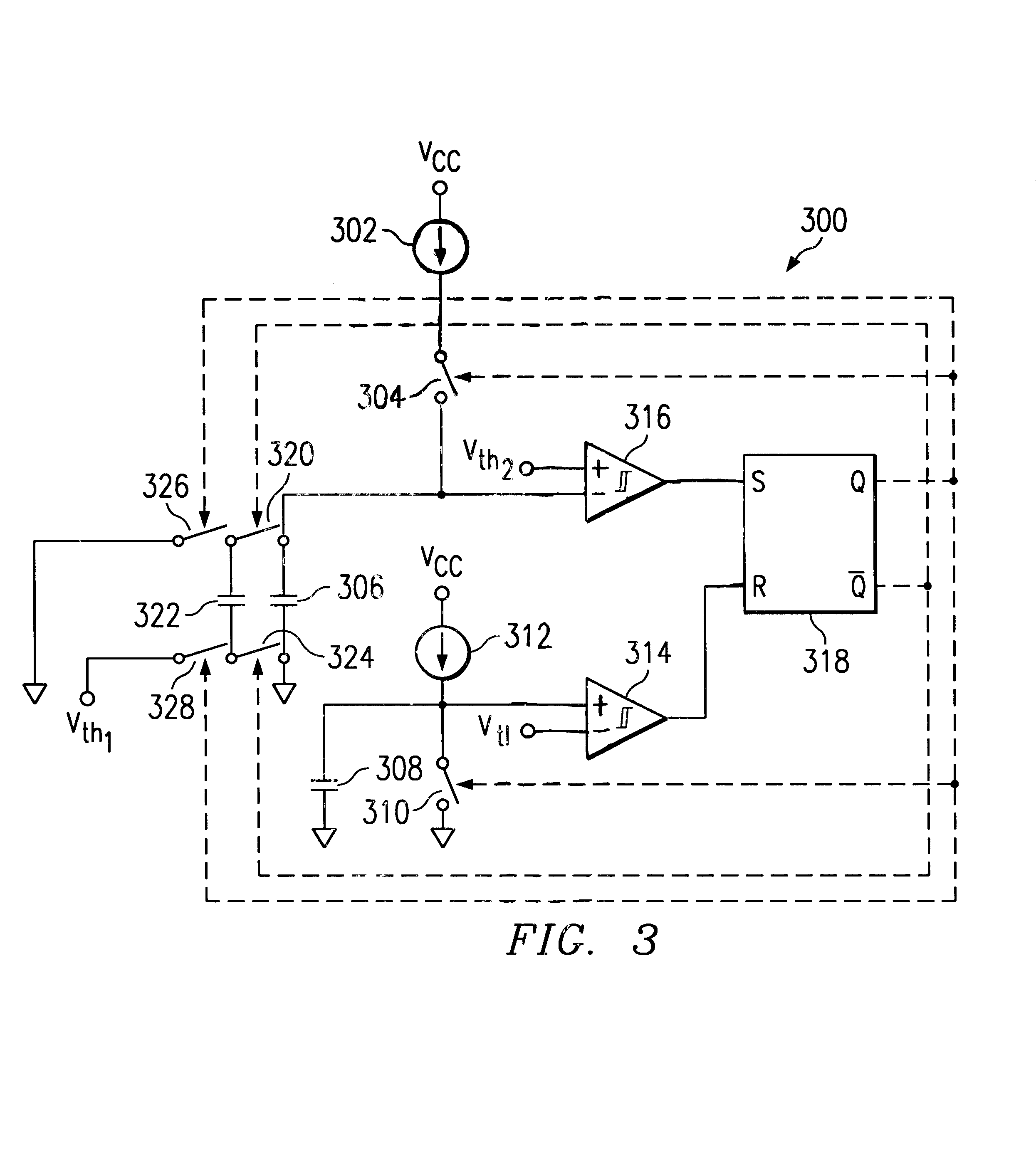
third embodiment
Accordingly, a third embodiment may include a logic delay connected between switches 320 and 324 and the inverted output .about.Q of flip-flop 318, such that switches 320 and 324 close after switches 326 and 328 open. This will eliminate any possibility of capacitor 322 discharging prematurely.
Those of skill in the art will recognize that the physical location of the elements illustrated in FIGS. 2 and 3 can be moved or relocated while retaining the function described above.
Advantages of this design include but are not limited to an oscillator having a high performance, simple, and cost effective design.
PUM
 Abstract
Description
Claims
Application Information